- FIBER OPTIC TRANSCEIVERS >800G & 400G Transceivers >400G QSFP-DD 30 km
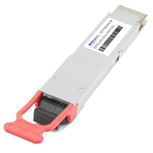
400G QSFP-DD 30 km
The Ascent QSFP-DD-ER4L-30 is a high-performance hot-pluggable optical transceiver designed for 400 Gigabit Ethernet applications requiring transmission distances of up to 30 km over single-mode fiber. Fully compliant with the QSFP-DD MSA, CMIS, and IEEE 802.3bs electrical interface specifications, the module provides reliable and cost-effective optical connectivity for cloud data centers, enterprise backbone networks, metro aggregation, and telecom transport applications. The transceiver employs four LAN-WDM optical wavelengths, each operating at 106.25 Gb/s PAM4, to deliver an aggregate data rate of 425 Gb/s through a duplex LC optical interface. Advanced EML transmitters, PIN receivers, and an integrated DSP architecture ensure excellent signal integrity, low latency, and outstanding optical performance while maintaining low power consumption. Supporting comprehensive Digital Diagnostic Monitoring (DDM) through the CMIS management interface, the module enables real-time monitoring of temperature, voltage, optical power, and laser bias current. Its compact QSFP-DD form factor, high reliability, and broad platform compatibility make it an ideal solution for next-generation Ethernet switches, routers, AI infrastructure, data center interconnect (DCI), and carrier networks.
· Supports 400GBASE-ER4-30
· Lane bit rate 106.25Gb/s with PAM4
· Up to 30km transmission on SMF
· 8x53.125Gb/s with PAM4 electrical interface (400GAUI-8)
· I2C interface with integrated Digital Diagnostic monitoring
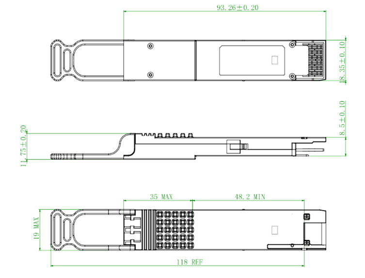
· QSFP-DD MSA package with duplex LC connector
· Single +3.3V power supply
· Maximum power consumption 12W
· Operating case temperature: 0 to +70°C
· Compliant to QSFP-DD CMIS standard
· Compliant to 802.3bs& QSFP-DD Hardware Specification
· Complies with EU Directive 2015/863/EU
Absolute Maximum Ratings
Parameter | Symbol | Min. | Typ. | Max. | Unit | Note |
Storage Temperature | TS | -40 | - | +85 | °C | |
Supply Voltage | VCC | -0.5 | - | +3.6 | V | |
Operating Relative Humidity | RH | 5 | - | +85 | % |
Recommended Operating Conditions
Parameter | Symbol | Min. | Typ. | Max. | Unit | Note |
Operating Case Temperature | TC | 0 | - | +70 | °C | |
Power Supply Voltage | VCC | 3.13 | 3.3 | 3.47 | V | |
Maximum Power Consumption | PD | - | - | 12 | W | |
Aggregate Bit Rate | BRAVE | - | 425 | - | Gb/s | With PAM4 |
Lane Bit Rate | BRLANE | - | 106.25 | - | Gb/s | With PAM4 |
Transmission Distance | TD | - | - | 30 | km | Over SMF |
Optical Characteristics
Transmitter | ||||||
Parameter | Symbol | Min. | Typ. | Max. | Unit | Note |
Center Wavelength Lane 0 | λ0 | 1304.06 | 1304.58 | 1305.1 | nm | |
Center Wavelength Lane 1 | λ1 | 1306.33 | 1306.85 | 1307.38 | nm | |
Center Wavelength Lane 2 | λ2 | 1308.61 | 1309.14 | 1309.66 | nm | |
Center Wavelength Lane 3 | λ3 | 1310.9 | 1311.43 | 1311.96 | nm | |
Average Launch Power per Lane | PTX_LANE | 0 | - | 5.6 | dBm | 1,2 |
OMAouter per Lane | OMAouter | 3 | - | 6.4 | dBm | |
Transmitter and Dispersion Eye Closure for PAM4 (TDECQ), per Lane | TDECQ | - | - | 3.9 | dB | |
Channel Power Difference | PTX_Delta | - | - | 3 | dB | |
Average Output Power (Laser Turn Off) | POUT-OFF | - | - | -15 | dBm | |
Side Mode Suppression Ratio | SMSR | 30 | - | - | dB | |
Extinction Ratio | ER | 5 | - | - | dB | |
Receiver | ||||||
Center Wavelength Lane 0 | λ0 | 1304.06 | 1304.58 | 1305.1 | nm | |
Center Wavelength Lane 1 | λ1 | 1306.33 | 1306.85 | 1307.38 | nm | |
Center Wavelength Lane 2 | λ2 | 1308.61 | 1309.14 | 1309.66 | nm | |
Center Wavelength Lane 3 | λ3 | 1310.9 | 1311.43 | 1311.96 | nm | |
Damage Threshold, per Lane | Pdamage | -2.4 | - | - | 3 | |
Average Rx Power per Lane | PRx _LANE | -14.7 | - | -3.4 | dBm | 4 |
Receiver Sensitivity (OMAouter), per Lane | Sens_OMA | - | - | -12.5 | dBm | 5 |
Notes:
1. The optical power is launched into SMF.
2. Average launch power, each lane (min) is informative and not the principal indicator of signal strength. A transmitter with launch power below this value cannot be compliant; however, a value above this does not ensure
compliance.
3. The receiver shall be able to tolerate, without damage, continuous exposure to an optical input signal having this average power level. The receiver does not have to operate correctly at this input power.
4. Average receive power, each lane (min) is informative and not the principal indicator of signal strength. A received power below this value cannot be compliant; however, a value above this does not ensure compliance.
5. Receiver sensitivity (OMAouter),each lane (max) is defined with BER=2.4E-4.
Electrical Characteristics
High-Speed Signal: Compliant to 400GAUI-8 (IEEE 802.3bs)
Low-Speed Signal: Compliant to QSFP-DD Hardware
Parameter | Symbol | Min. | Typ. | Max. | Unit | Note |
Differential Data Input Amplitude | VIN,P-P | 900 | - | - | mVpp | |
Differential Termination Mismatch | - | - | 10 | % | ||
Receiver (Module Output) | ||||||
Differential Data Output Amplitude | VOUT,P-P | - | - | 900 | mVpp | |
Differential Termination Mismatch (1MHZ) | - | - | 10 | % | ||
Low-speed Electrical Interface | ||||||
LPMode/TxDis, ResetL, ModSelL and EPPS/Clock | VIL | -0.3 | - | 0.8 | V | |
VIH | 2.0 | - | VCC+0.3 | V | ||
ModPrsL | VOL | 0 | - | 0.4 | V | |
VIH | ModPrsL can be implemented as a short-circuit to GND on the module | |||||
IntL/RxLOS | VOL | 0 | - | 0.4 | V | |
VOH | VCC-0.5 | - | VCC+0.3 | V | ||
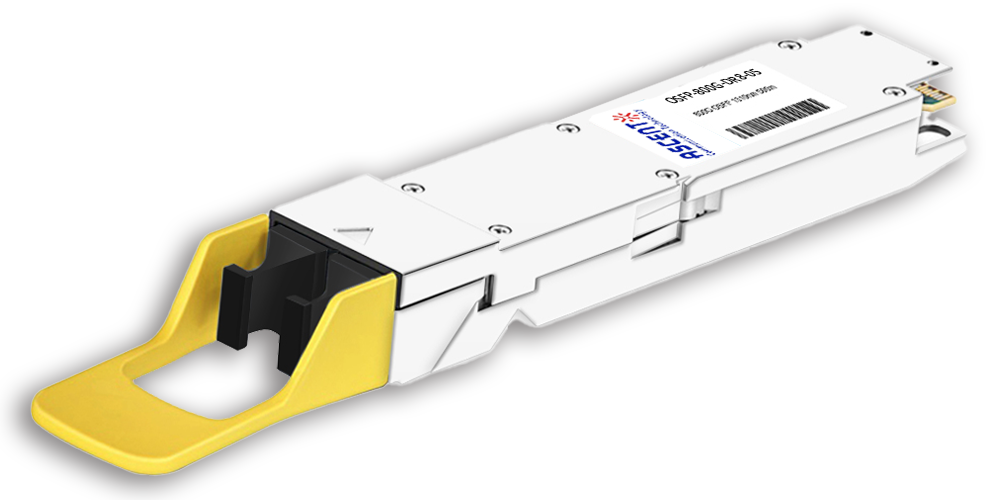
800G OSFP DR8 1310 nm 500 m
800 Gb/s DR8 OSFP 500m Optical Transceiver
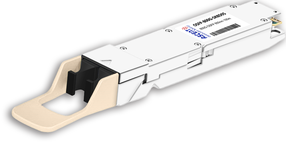
800G OSFP SR8 850 nm 100 m
OSFP-800G-SR8D-01 800 Gb/s OSFP SR8 850 nm 100 m Transceiver
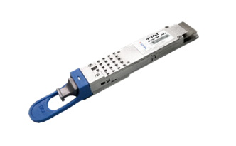
400G QSFP56-DD 10km
400G QSFP-DD 4X100G LR1 Optical Transceiver
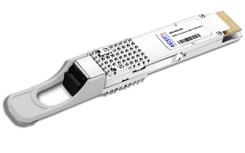
400G QSFP-DD ZR+
QSFP-DD-ZR-80 400 Gb/s QSFP-DD 80 km Transceiver
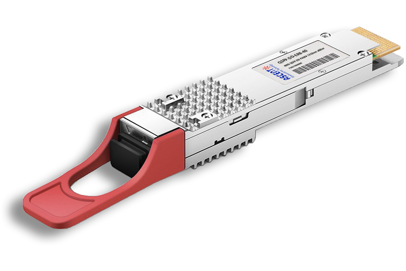
400G QSFP-DD ER8 40 km
QSFP-DD-ER8-40 400 Gb/s QSFP-DD 40 km Transceiver
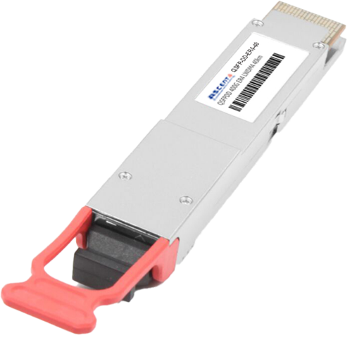
400G QSFP-DD 40 km
400 Gb/s QSFP-DD 40 km Transceiver
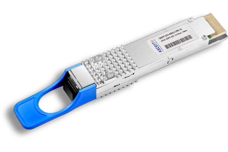
400G QSFP-DD LR8 1310 nm 10 km
QSFP-DD-LR8-10 400 Gb/s QSFP-DD LR8 10 km Transceiver

400G QSFP-DD LR4 CWDM 10 km
QSFP-DD-LR4-10 400 Gb/s QSFP-DD LR4 CWDM 10 km Transceiver
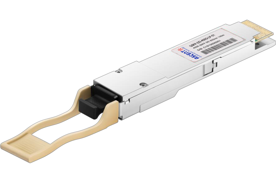
400G QSFP-DD SR8 850 nm 100 m
QSFP-DD-LP-01 400 Gb/s QSFP-DD SR8 100 m Transceiver
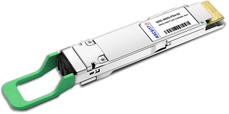
400G QSFP-DD FR4 2km
400 Gb/s QSFP-DD FR4 2 km DDM Transceiver
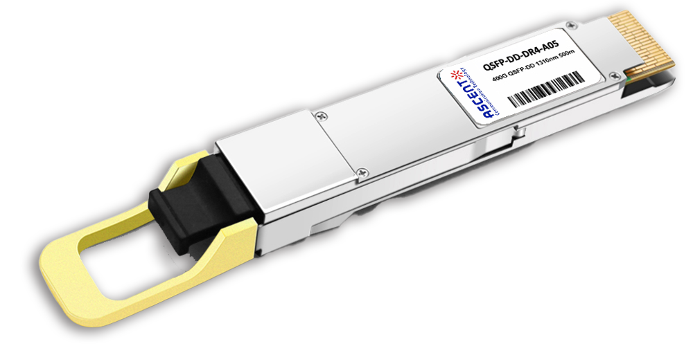
400G QSFP-DD DR4 500m
400 Gb/s QSFP-DD DR4 500m Transceiver
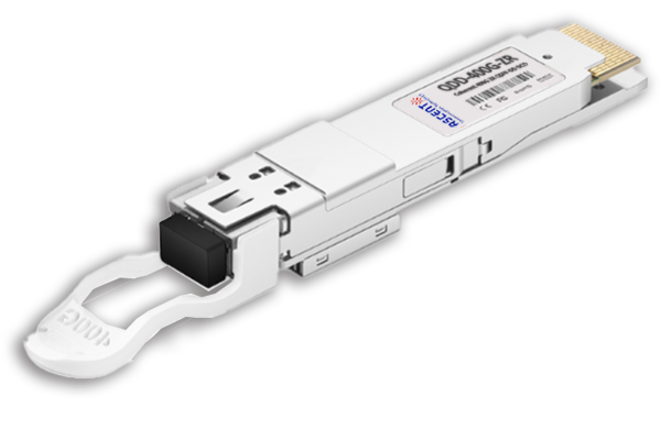
400G QSFP-DD DCO ZR
400G QSFP-DD DCO ZR Coherent Optical Transceiver
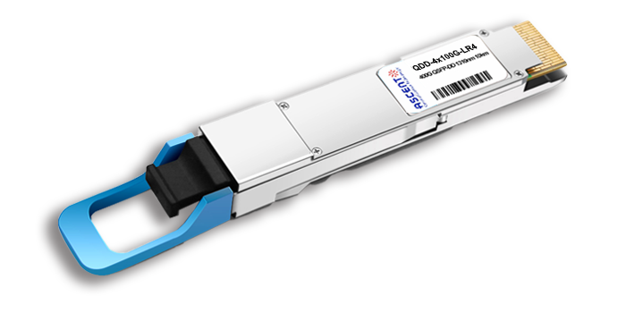
4X100G QSFP-DD LR4 10km
QDD 4x100G 1310nm LR 10 km Transceiver
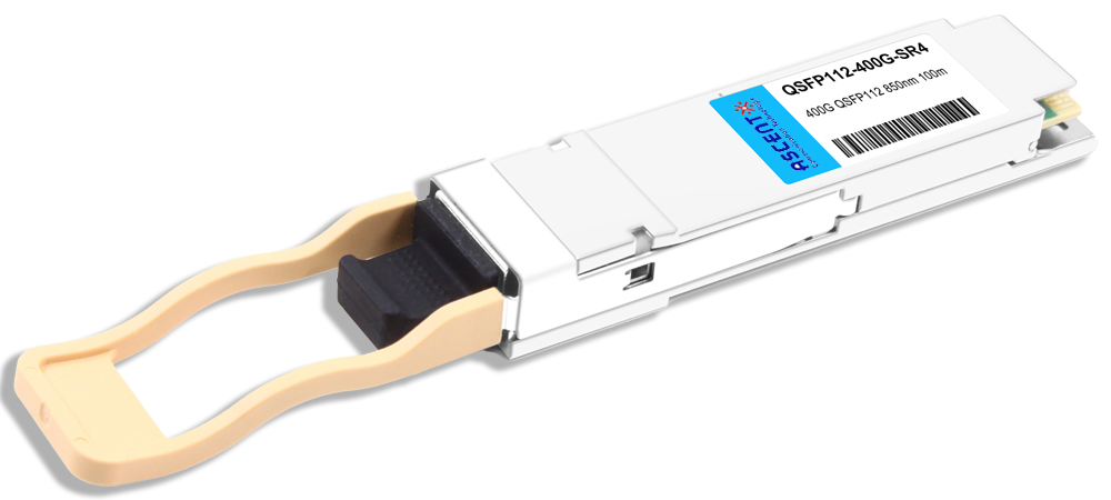
400G QSFP112 SR4 850 nm 100 m
QSFP112-400G-SR4-01 400 Gb/s QSFP112 SR4 850 nm 100 m Transceiver
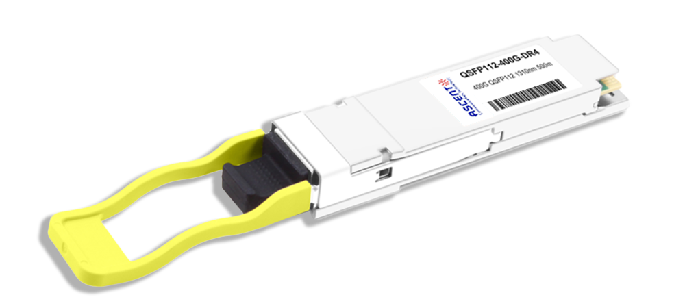
400G QSFP112 DR4 1310 nm 500 m
400G QSFP112 DR4 1310 nm Transceiver 500m
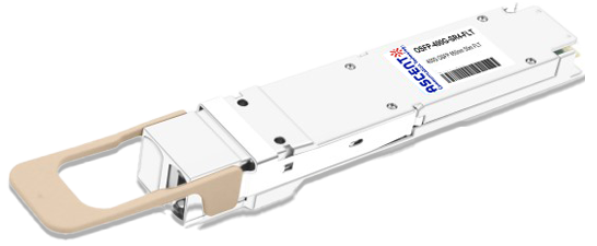
400G OSFP SR4 FLT 50m Transceiver
400 Gbps Multi-Mode 50m OSFP Transceiver
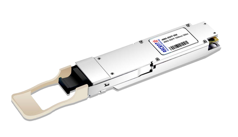
400G OSFP SR8 100m Transceiver
400 Gbps PSM8 Multi-Mode 100m OSFP Transceiver
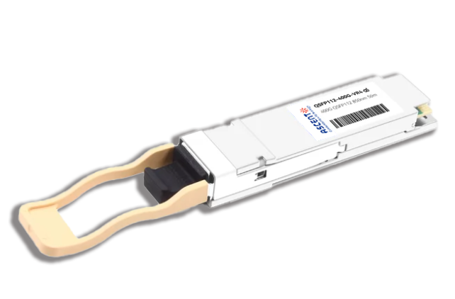
400G QSFP112 VR4 Transceiver
400G QSFP112 VR4
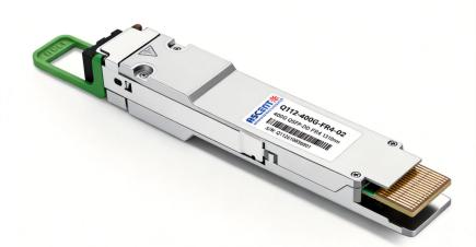
400G QSFP 112 FR4 2km Transceiver
Q112-400G-FR4-02
White Paper
Press Releases
Briefings 1
Briefings 2
Videos, etc.
QRG
Manual1
Manual2
Get in touch with our experts
Feedback