- FIBER OPTIC TRANSCEIVERS >40G & 25G Transceivers >32G SFP28 1310 nm 10 km
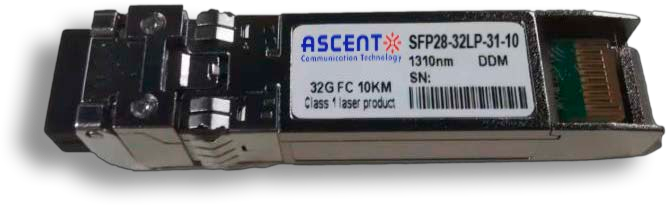
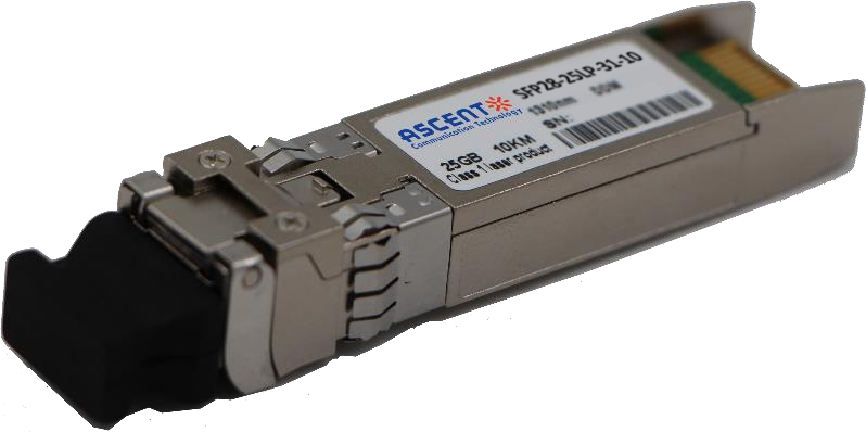
32G SFP28 1310 nm 10 km
Ascentãs SFP28 32 Gb/s transceiver is an integrated ÿ˜ber optic transceiver that provides a high-speed serial link at signaling rates up to 28.05 Gb/s. It is a single-channel, pluggable, fiber-optic module for short and medium-range data communication and interconnect Ethernet applications. This module is designed to operate over single- mode fiber systems using a nominal wavelength of 1310 nm. It has a transmission distance of up to 10 km over SMF. The optical interface uses duplex LC receptacle. The SFP28-32LP-31-10 module complies with SFF-8431 and SFF 8472 standards. It features a metal enclosure for lower EMI and utilizes a 2- wire interface that is compliant with the serial communication protocol as defined in the SFP+ MSA. It also provides a unique integrated digital diagnostic monitoring interface, allowing for real-time access to device operating parameters. This module is hot-pluggable.
ôñ Up to 28.05 Gb/s bit rates
ôñ Up to 10 km transmission on SMF
ôñ DFB Laser and PIN receiver
ôñ Metal enclosure, for lower EMI
ôñ 2-wire interface with integrated Digital Diagnostic monitoring
ôñ Compliant with SFP+ MSA with LC connector
ôñ Single 3.3V power supply
ôñ Power consumption < 1.5 W
ôñ Case operating temperature range: commercial: 0ô¯C to +70ô¯C, extended: 0ô¯C to +85ô¯C
ôñ Compliant to SFF-8431
ôñ Compliant to SFF 8472
ôñ RoHS Compliant
Absolute Maximum Ratings
Parameter Storage Temperature | Symbol Ts | Min.
| Typ.
| Max.
| Unit Note |
Relative Humidity | RH | 5 | - | 95 | % |
Power Supply Voltage | VCC | -0.5 | - | 4.0 | V |
Signal Input Voltage | Vcc-0.3 | - | Vcc+0.3 | V |
Recommended Operating Conditions
Parameter Case Operating Temperature | Symbol Tcase | Min. 0 | Typ. - | Max. 70 | Unit ô¯C | Note Commercial |
0 | - | 85 | ô¯C | Extended | ||
Power Supply Voltage | VCC | 3.14 | 3.30 | 3.47 | V | |
Power Supply Current | ICC | - | 450 | mA | ||
8.5 | Gbps | 1 | ||||
Data Rate | BR | 14.025 | ||||
28.05 | ||||||
Bit Error Rate | BER | 10-12 | Gbps | 2 | ||
10-6 | 3 | |||||
Transmission Distance | ||||||
Coupled Fiber | Single-mode fiber | |||||
Notes:
1. 8x, Fibre Channel compatible, per FC-PI-41.
2. PRBS 27-1 for 8GFC. PRBS 231-1 for 16GFC.
3. FEC for 32GFC.
Optical Characteristics
Parameter Transmitter | Symbol | Min. | Typ. | Max. | Unit | Note |
Average Output Power, 28.05 Gb/s & 14.025 Gb/s | POUT | -5 | +2.0 | dBm | 1, 2 | |
Average Output Power, 8.5 Gb/s | POUT | -8.4 | +0.5 | dBm | 1 | |
Optical Wavelength | ö£ | 1295 | 1325 | nm | ||
Spectral Width (RMS) | ü | 1 | nm | |||
Optical Modulation Amplitude | ||||||
8.5 Gb/s | OMA | -5.4 | +3 | dBm | ||
14.025 Gb/s | -2.0 | |||||
28.05 Gb/s | -2.0 | |||||
Transmitter Dispersion Penalty | ||||||
8.5 Gb/s | TDP | 3.2 | dB |
14.025 Gb/s | 4.4 | ||||
28.05 Gb/s | 2.7 | ||||
Optical Extinction Ratio | |||||
8.5 Gb/s & 14.025 Gb/s | ER | 3.5 | dB | ||
28.05 Gb/s | 4.0 | ||||
Relative Intensity Noise | |||||
8.5Gb/s | RIN | -128 | dB/Hz | ||
14.025Gb/s | -130 | ||||
28.05Gb/s | -130 | ||||
Receiver | |||||
Unstressed Receiver OMA Sensitivity | |||||
8.5 Gb/s | RSENS | -13.8 | dBm | 3 | |
14.025 Gb/s | -12.0 | ||||
28.05 Gb/s | -11.4 | ||||
Average Receiver Power | RxMAX | 2 | dBm | ||
Optical Return Loss | |||||
8.5 Gb/s & 14.025 Gb/s | 12 | dB | |||
28.05 Gb/s | 26 | ||||
LOS De -Assert | LOSD | -17 | dBm | ||
LOS Assert | LOSA | -30 | dBm | ||
LOS Hysteresis | 0.5 | dB |
1. Class 1 Laser Safety limit per FDA/CDRH, and EN (IEC) 60825 laser safety standards.
2. 3200-SM-LC-L OMA in dBm shall also exceed -5.0 TDP.
3. For 32GFC with FEC, receiver sensitivity is defined at 10-6 BER level, not 10-12 BER level.
Electrical Characteristics
Parameter | Symbol | Min. | Typ. | Max. | Unit | Note |
Supply Voltage | Vcc | 3.14 | 3.3 | 3.46 | V | |
Supply Current | Icc | 450 | mA | 1 | ||
Transmitter | ||||||
Input Differential Impedance | Rin | 100 | öˋ | 2 | ||
Differential Data Input Eye Height | Vin, pp | 250 | 900 | mV | 2 | |
Transmit Disable Voltage | VD | Vccã1.3 | Vcc | V | 3 | |
Transmit Enable Voltage | VEN | Vee | Vee+ 0.8 | V | ||
Receiver | ||||||
Differential Data Output Swing | Vout, pp | 300 | 1000 | mV | 4 | |
LOS Fault | VLOS fault | Vccã1.3 | VccHOST | V | 5 | |
| LOS Normal | VLOS | Vee | Vee+0.8 | V | 5 |
1. With established link, the total power dissipation shall not exceed 1.3 W/
2. Connected directly to TX data input pins. AC coupling from pins into CDR, BER contour 10-6
3. Or open circuit.
4. Into 100 öˋ differential termination.
5. LOS is an open collector output. Should be pulled up with 4.7 köˋ to 10 köˋ on the host board. Normal operation is logic 0; loss of signal is logic 1. Maximum pull-up voltage is 5.5 V.


64G SFP56 850nm 100m
64 Gb/s SFP56 SW Fibre Channel 850nm Transceiver
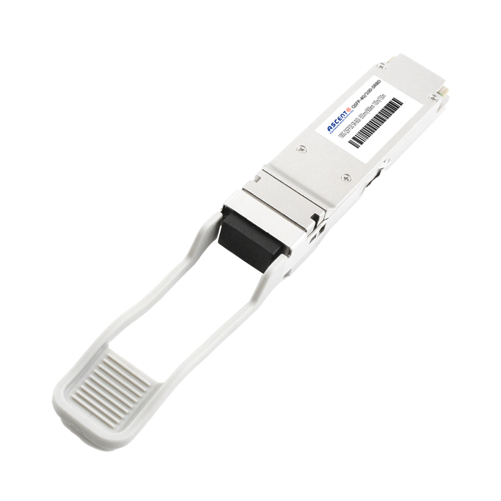
40/100G SFP28 SWDM4 100m
40/100Gb/s QSFP28, Bi-Di, Duplex LC 100m Transceiver

40G QSFP+ ER4 Industrial 40 km
40 Gb/s QSFP+ ER4 40 km Transceiver

40G QSFP+ ER4 40 km
40 Gb/s QSFP+ ER4 40 km Transceiver

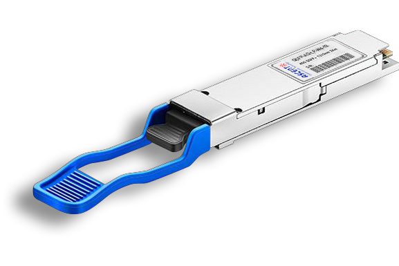
40G QSFP+ LR4 Industrial 10 km
40 Gb/s QSFP+ LR4 10 km Transceiver

40G QSFP+ LR4 10 km
QSFP-AQ-LP-W4-10 40 Gb/s QSFP LR4 10 km Transceiver

40G QSFP+ PSM4 2 km
40 Gb/s QSFP+ PSM4 Transceiver 2km
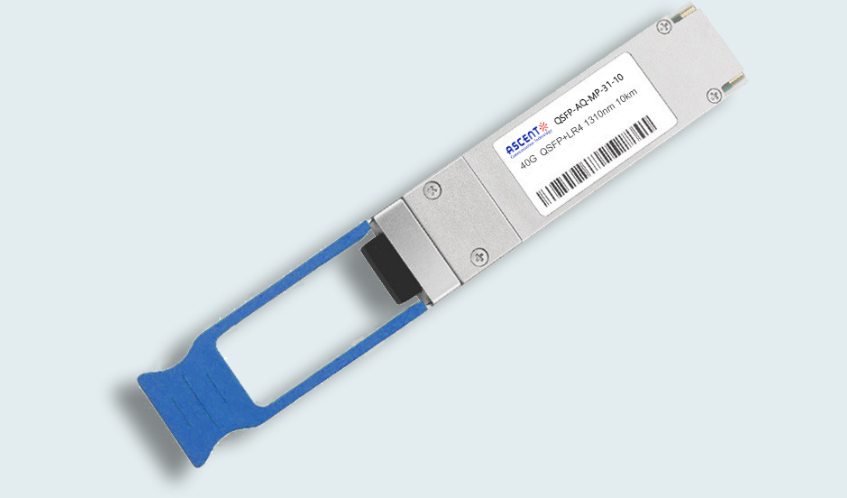
40G QSFP+ PLR4 1310 nm 10 km
QSFP-AQ-MP-31-10 40 Gb/s QSFP+ PSM 1310nm 10km MPO Optical Transceiver

40G QSFP+ CSR4 300m
40 Gb/s 300m QSFP+ CSR4 Transceiver
40GBASE-UNIV QSFP+ MMF and SMF
40G QSFP+ UNIV MMF/SMF 150m/2km
40G QSFP+ CWDM 2 km
40G QSFP+ CWDM 2 km
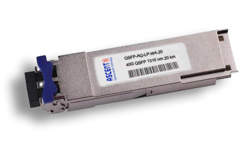
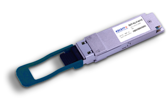
40G QSFP CWDM 20 km
QSFP-AQ-LP-W4-20 40 Gb/s QSFP CWDM 20 km Transceiver
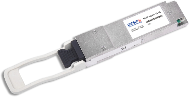
40G QSFP+ SR4 300 m
40 Gb/s QSFP+ SR4 Transceiver with DDM
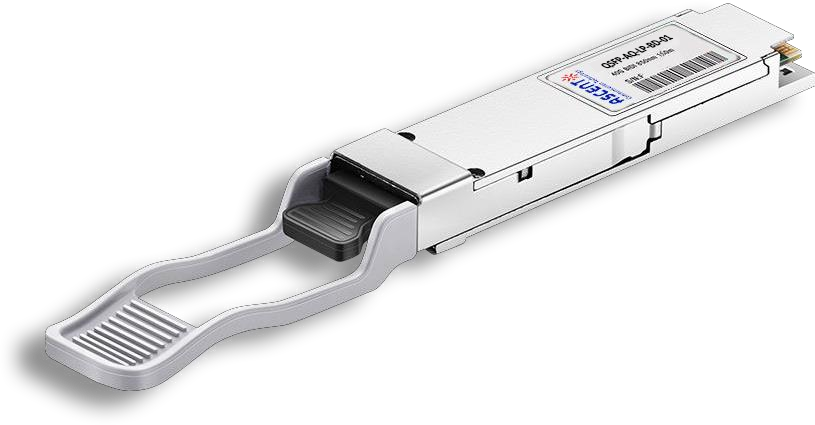
40G QSFP+ BIDI 150m
40 Gb/s QSFP+ BiDi Transceiver 150m

32G SFP28 SR 850 nm 100 m
SFP28-32LP-85-01 32GBASE-SR SFP28 850 nm 100 m DOM Transceiver
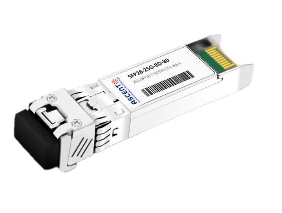
25G SFP28 BIDI 80 km
25G SFP28 BIDI 80 km Transceiver
.png)
25G SFP28 CWDM 10 km(E)
25 Gb/s CWDM EML SFP28 10 km Transceiver
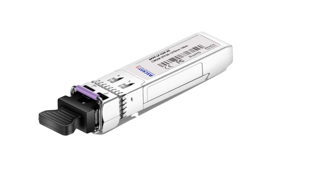
25G SFP28 CWDM 10 km(D)
25 Gb/s CWDM SFP28 10 km Transceiver
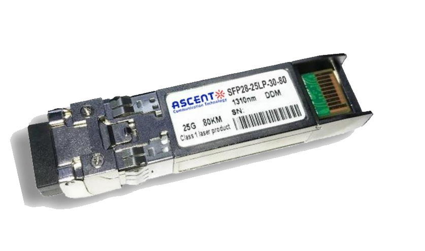
25G SFP28 ZR 1310nm 80km
25 Gbps 1310 nm 80 km SFP28 ZR Transceiver
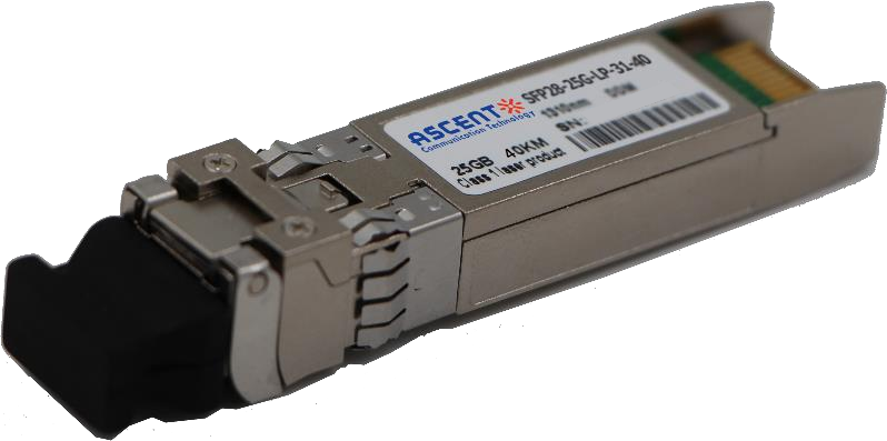
25G SFP28 1310 nm 40km
25 Gb/s 1310 nm Single-Mode SFP28 Transceiver
25G SFP28 1310 nm 10 km
SFP28-25LP-31-10 25 Gb/s 1310 nm Single-Mode SFP+ Transceiver
25G SFP28 850 nm 300m
25 Gb/s 850 nm Multi-Mode SFP28 300m Transceiver
25G SFP28 850 nm 100m
SFP28-25LP-85-01 28 Gb/s 850 nm Multi-Mode SFP28 Transceiver

10/25G SFP28 1310nm 40km
10/25 Gb/s SFP28 1310 nm 40km Transceiver
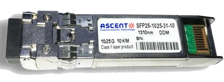
10/25G SFP28 1310nm 10km
10/25 Gb/s SFP28 1310 nm 10km DDM Transceiver

10/25G SFP28 850 nm 300m
10/25 Gb/s SFP28 850 nm 300m Transceiver

10/25G SFP28 850 nm 100m
10/25 Gb/s SFP28 850 nm 100m Transceiver
White Paper
Press Releases
Briefings 1
Briefings 2
Videos, etc.
QRG
Manual1
Manual2
Get in touch with our experts
Feedback