- HFC CABLE TV >RF Amplifiers >ARF120H RF AMP
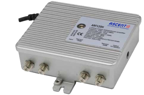
ARF120H RF AMP
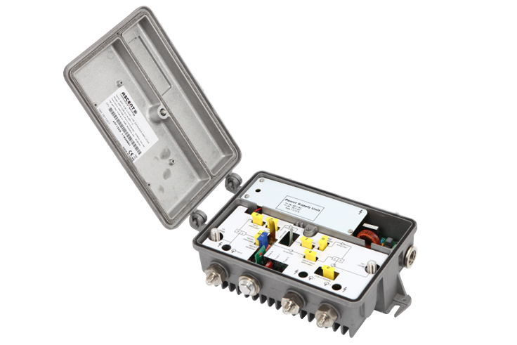
ARF120H Series 1.2 GHz Two-way GaAs RF amplifier is part of ACT Advanced Fiber Deep HFC solution, which has been designed to deliver interactive CATV, high capacity DOCSIS and other advanced services. The cost effective last mile amplifier platform helps operators expand bandwidth of their existing HFC network while minimizing capital investment. The ARF120H amplifier has compact housing with embedded RF module and is suitable for MDU, FTTB or FTTC applications with output to 107 dBö¥V. The ARF120H 1.2 GHz GaAs RF amplifier adopts E-pHEMT Push Pull distribution technology, that guarantees the excellent CTB and CSO performance and suitable for upgrade to DOCSIS 3.1. ARF120H RF amplifier has low power consumption and supports local or remote power options. Combined with ACTãs converged headend AH1000 optical system and AON node series, ARF120H is an ideal product to provide MSOs with an economical, flexible HFC access solution.
ôñ Supports 1.2 GHz bandwidth
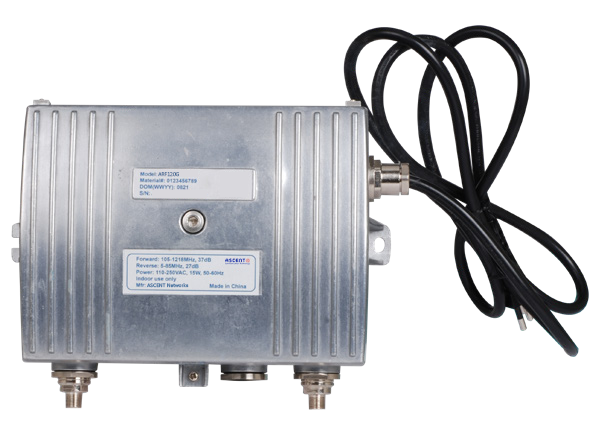
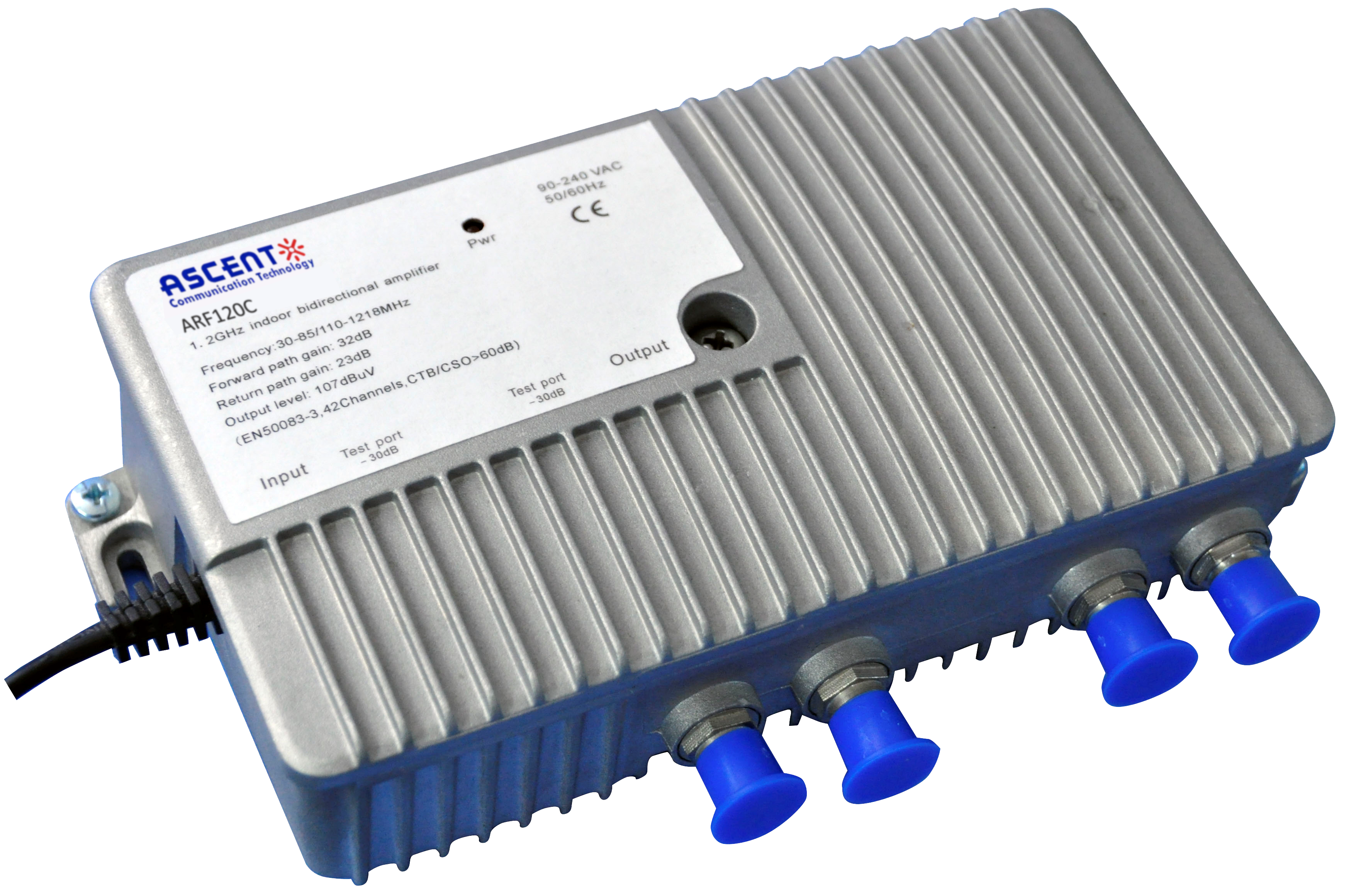
ôñ Indoor bidirectional amplifier
ôñ Compact design, small and exquisite
ôñ Improved ESD and surge protection
ôñ Low noise figure
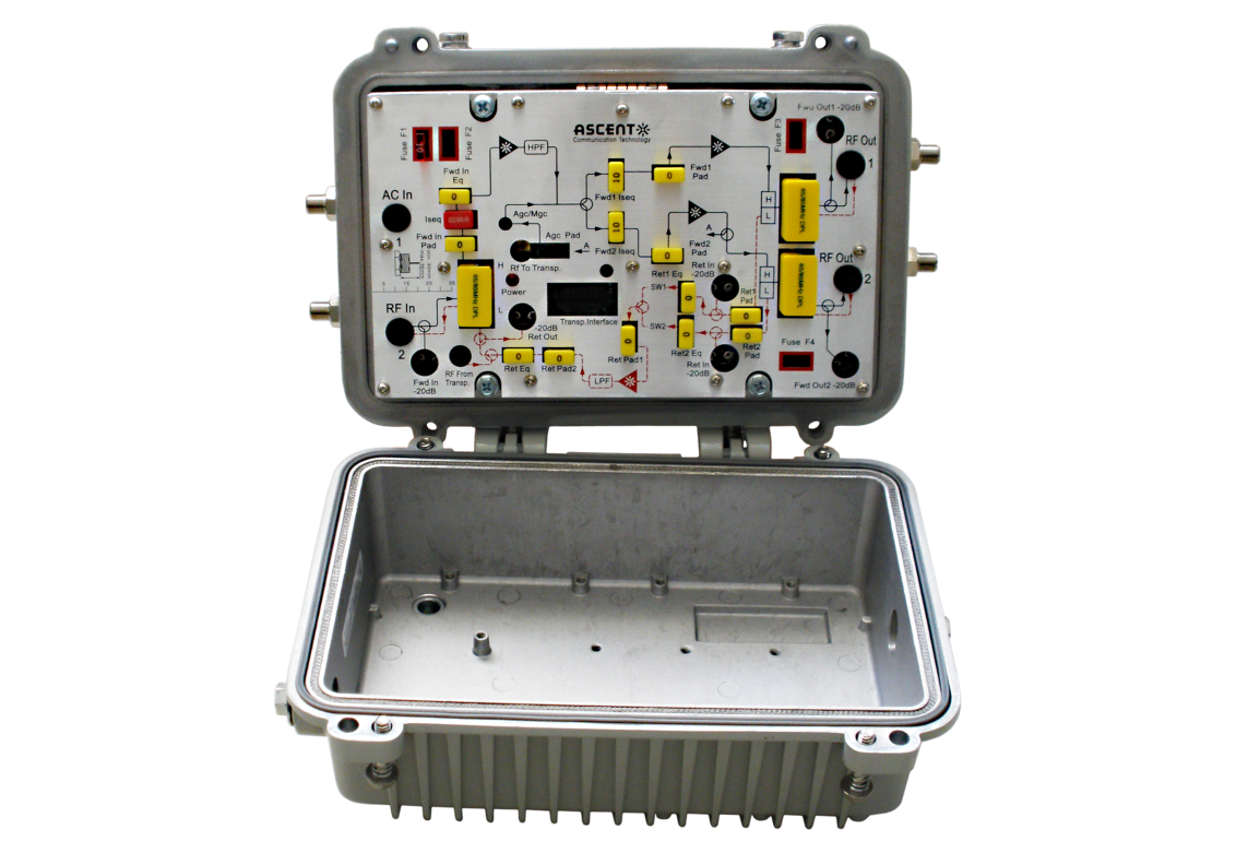
ôñ Standard JXP plug-in PADs for adjustments of attenuation and forward input equalization
ôñ Plug-in DMC jumper for adjustments of forward interstage and reverse equalization
ôñ Gain adjustment 0 to 18 dB (AGC)
Forward Path Characteristics
Item | Unit | Technical Parameters |
Pass Band | MHz | 110/258 to 1218 |
Gain | dB | 35 |
Frequency Response | dB | ôÝ1.0 |
Reference Output Level (CENELEC 42 channel) CSO: 60dB CTB: 60dB | dBpV | >=107 |
Gain Adjustment | dB | 0 to min.18 dB (AGC) |
Input Equalizer Adjustable | dB | 0 to 20 dB 1 dB step, Adjust via JXP PAD |
Interstage Equalizer Adjustable | dB | 0, 4, 8 Adjust dvia DMC Jumper |
Return Loss | dB | 16 |
RF Test Point | dB | -30 |
Noise Figure | dB | ãÊ7 |
1. Forward Gain and Noise Figure measured with 0 dB input EQ and 0 dB input pad.
2. Distortion performance reference output level is 107 dBôçV (CENELEC 42 channel, flat). Digital refers to 550 MHz to 1.2 GHz loading with QAM carriers at -6 dB relative to analog CW carrier levels.
Return Path Characteristics
Item | Unit | Technical Parameters |
Pass Band | MHz | 5 to 85/204 |
Gain | dB | 30 |
Gain Control (Input & Output) | 0 to 20 dB 1 dB step, Adjust via JXP PAD | |
Equalizer Adjustable | dB | 0, 4 Adjust via DMC Jumper |
Frequency Response | dB | ôÝ1.0 |
Return Loss | dB | 18 |
RF Test Point | dB | -30 |
Noise Figure | dB | ãÊ6 |
General Characteristics
Power Consumption (High Gain / Low Gain) | W | ãÊ5 |
Supply Voltage (AC) | V | 26 to 65 V (remote PS) / 220 V (local PS) |
RF Connectors | - | F - female, Imperial |
Dimensions (W x H x D) | mm | 105 x 125 x 50 |
Weight | kg | 0.70 |
Mechanical Enclosure | - | IP 54 class protection, diecast housing |
Operating Temperature | ô¯C | -40 to + 55 |
Storage Temperature | ô¯C | -40 to + 80 |
Relative Humidity Range | - | 5% to 95% |

ARF230 RF AMP
ARF230 High-Output Two-Way Trunk/Line Amplifier

ARF130C Trunk AMP
MDU 1 or 2 O/P Trunk Amplifier
ARF120G MDU AMP
1.2 GHz MDU Amplifier
ARF120C MDU AMP
1.2GHz MDU Amplifier Deep Fiber Solution
ARF120 RF AMP
ARF120B 1.2 GHz GaAs MDU Amplifier

ARF110C Trunk AMP
MDU 1 or 2 -port Line Amplifier
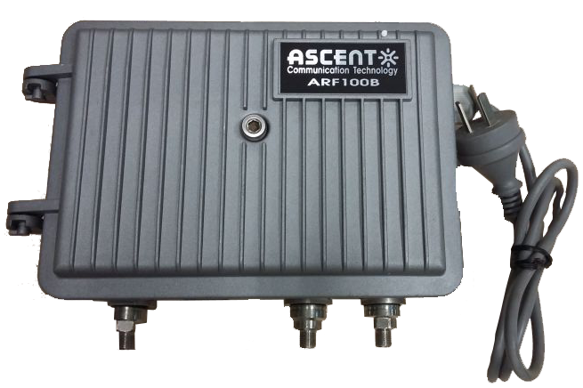
ARF100B LE AMP
ARF100B 1 or 2 RF Outputs MDU Amplifier
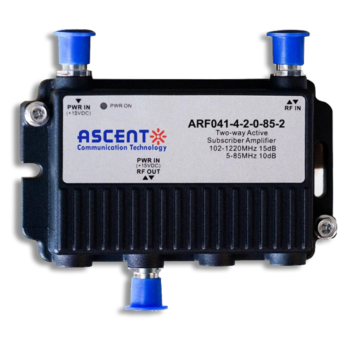
ARF040 RF AMP
Bi-Directional House Amplifier
White Paper
Press Releases
Briefings 1
Briefings 2
Videos, etc.
QRG
Manual1
Manual2
Get in touch with our experts
Feedback