- FIBER OPTIC TRANSCEIVERS >10G Transceivers >10G SFP+ Tunable DWDM 80 km
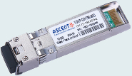
10G SFP+ Tunable DWDM 80 km
Ascentãs SFPP-LP-T99R-80 10 Gb/s SFP+ tunable transceiver is an integrated ÿ˜ber optic transceiver that provides a high-speed serial link at signaling rates from 9.95 Gb/s to 11.3 Gb/s. The module complies with the 10 Gigabit Enhanced Small Form Factor Pluggable (SFP+) multisource agreement - MSA(SFF-8431) and SFF-8432, SFF-8690, and SFF 8472. It complies with the ITU-T G.698.1 standard with 50 GHz channel spacing for SONET/SDH, IEEE DWDM 10GBASE-ZR for up to 80 km (Ethernet), and DWDM 10GFC for up to 80 km (Fiber Channel) applications.
ã Supports 9.95 Gb/s to 11.3 Gb/s bit rates
ã Monolithically integrated full C-band tunable transmitter and APD receiver
ã 50 GHz ITU channel spacing with integrated wavelength locker
ã Maximum link length of 80km
ã Metal enclosure, for lower EMI
ã 2-wire interface with integrated Digital Diagnostic monitoring
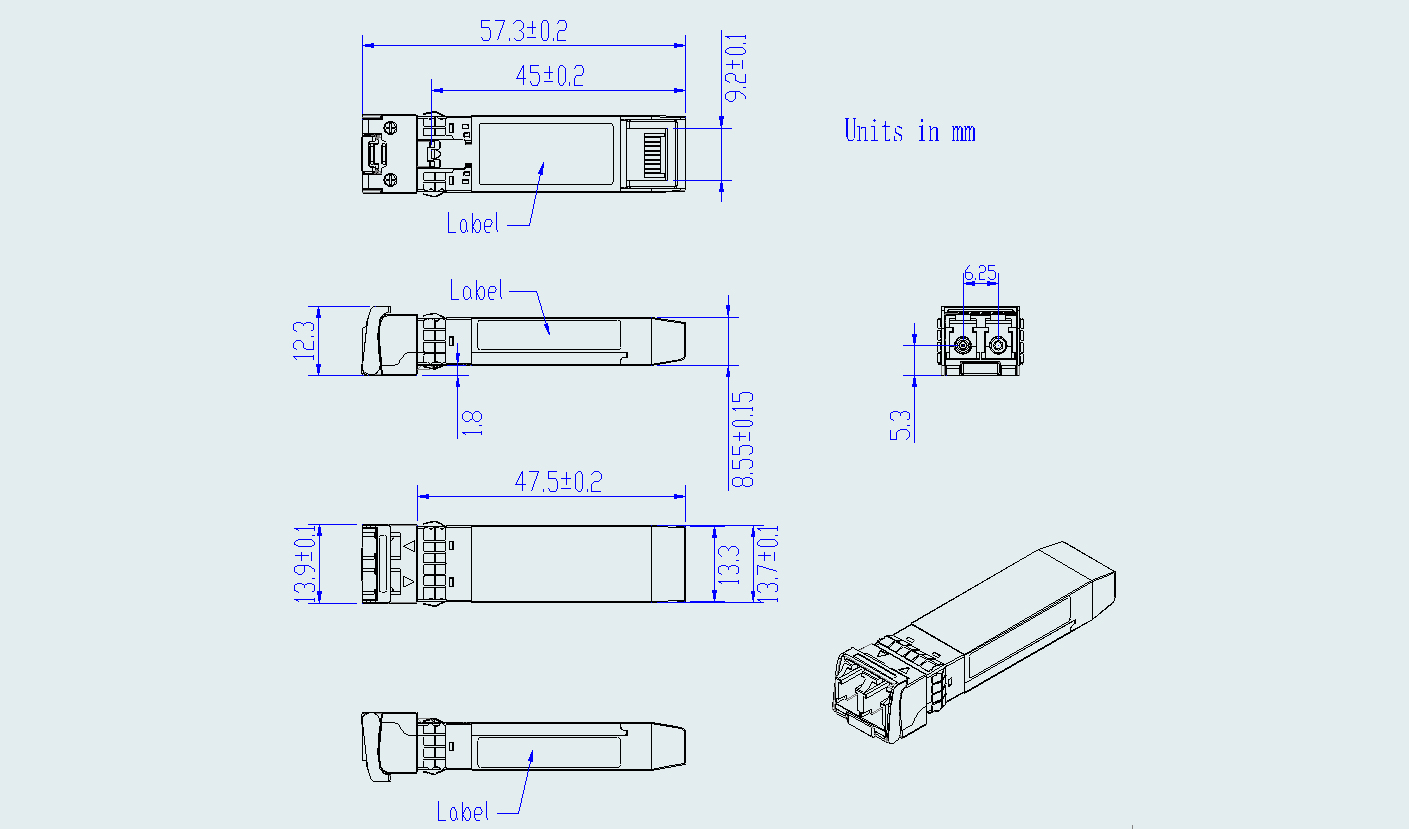
ã Hot-pluggable SFP+ footprint
ã Specifications compliant with SFF 8472 V10.3 & SFF 8690 V1.4
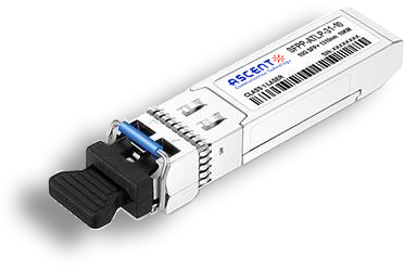
ã Compliant with SFP+ MSA with LC connector
ã Power dissipation<1.65 W
ã Case temperature range: -5 ô¯C to +70 ô¯C
Parameter | Symbol | Min. | Typ. | Max. | Unit | Note |
Storage Temperature | Ts | ã40 | ã | 85 | ô¯C | |
Relative Humidity | RH | 5 | ã | 85 | % | |
Power Supply Voltage | VCC | ã0.3 | ã | 3.6 | V | |
Signal Input Voltage | Vccã0.3 | ã | Vcc+0.3 | V |
Recommended Operating Conditions
Parameter | Symbol | Min. | Typ. | Max. | Unit | Note |
Case Operating Temperature | Tcase | ã5 | ã | 70 | ô¯C | Without air flow |
Power Supply Voltage | VCC | 3.14 | 3.3 | 3.47 | V | |
Power Supply Current | ICC | ã | 500 | mA | ||
Data Rate | BR | 10.3125 | Gbps | |||
Transmission Distance | TD | ã | 80 | km | ||
Coupled fiber | Singleãmode fiber | 9/125 ôçm SMF | ||||
Optical Characteristics
Parameter | Symbol | Min | Typ | Max | Unit | Note |
Transmitter | ||||||
Average Optical Power | Pout | ã1 | 3 | dBm | 1 | |
Frequency Stability (BOL) | ócã1.5 | óc+1.5 | GHz | 2 | ||
Frequency Stability (EOL) | ócã2.5 | óc+2.5 | GHz | 2 | ||
Center Wavelength Spacing | 50 | GHz | 3 | |||
Optical Extinction Ratio | ER | 8.2 | dB | |||
Side mode Suppression ratio | SMSR | 35 | dB | |||
Average Launch Power (Laser off) | Poff | ã30 | dBm | |||
Output Eye Mask | Compliant with IEEE 802.3ae | |||||
Receiver | ||||||
Rx Sensitivity with Dispersion 0 ps/nm | RSENS | ã23 | dBm | @9.95, 10.3, 10.5 Gbps, BER=10^ã12 | ||
ã27 | @10.709 Gbps, BER=10^ã4 | |||||
ã27 | @11.1 Gbps, BER=10^ã4 | |||||
ã26.5 | @11.3 Gbps, BER=10^ã4 | |||||
Rx Sensitivity with Dispersion ã400 ps/nm to +1450 ps/nm | ã21 | @9.95, 10.3, 10.5 Gbps, BER=10^ã12 | ||||
ã25 | @10.709 Gbps, BER=10^ã4 | |||||
ã25 | @11.1 Gbps, BER=10^ã4 | |||||
ã24 | @11.3 Gbps, BER=10^ã4 | |||||
Input Saturation Power (Overload) | Psat | ã6 | dBm | |||
Wavelength Range | ö£C | 1480 | 1580 | nm | ||
LOS DeãAssert | LOSD | ã27 | dBm | |||
LOS Assert | LOSA | ã36 | dBm | |||
LOS Hysteresis | 0.5 | dB | ||||
Notes:
1. Output power is power coupled into a 9/125 mm singleãmode fiber.
2. óc refers to Page 2 the Frequency row of SFPPãATãLPãT99Rã80 Wavelength Guide Table, and test condition is reflect power to transmitter lower than ã27 dBm.
3. Corresponds to approximately 0.4 nm.
Electrical Characteristics
Symbol | Min | Typ | Max | Unit | Note | |
Supply Voltage | Vcc | 3.14 | 3.3 | 3.46 | V | |
Supply Current | Icc | 500 | mA | |||
Transmitter | ||||||
Input Differential Impedance | ohm | 100 | öˋ | 1 | ||
Differential Data Input Swing | Vin, pp | 240 | 910 | mV | ||
Transmit Disable Voltage | Vdis | Vccã1.3 | Vcc | V | ||
Transmit Enable Voltage | Ven | Vee | Vee+0.8 | V | 2 | |
TX_FAULT VoltageãHigh | Vccã1.3 | Vcc | V | |||
TX_FAULT VoltageãLow | Vee | Vee+0.8 | V | |||
Receiver | ||||||
Differential Data Output Swing | Vout, pp | 350 | 800 | mV | 3 | |
Data Output Rise Time | tr | 30 | ps | 4 | ||
Data Output Fall Time | tf | 30 | ps | 4 | ||
LOS Fault | Vccã1.3 | VccHOST | V | 5 | ||
LOS Normal | Vee | Vee+0.8 | V | 5 |
Notes:
1. Connected directly to TX data input pins. AC coupled thereafter.
2. Or open circuit.
3. Into 100 ohms differential termination.
4. These are unfiltered 20 % to 80 % values
5. Loss Of Signal is LVTTL. Logic 0 indicates normal operation; logic 1 indicates no signal detected.
Timing Parameters
Parameter | Symbol | Min | Typ | Max | Unit | Note |
Time to Initialize Cooled Module | Tstart_up | 20 | s | |||
Channel Switch Time | TchannelSwitch | 200 | ms | Any channel to any channel |

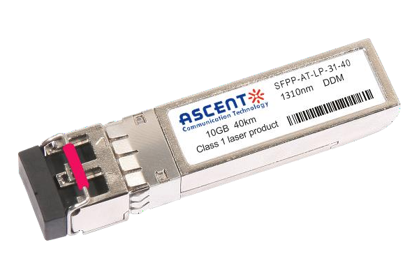
10G SFP+ LR 1310 nm 40 km
10 Gb/s 1310nm SFP+ 40 km Transceiver

10G SFP+ LR 1310 nm 20 km
SFPP-ATLP-31-20 SFP+ Plug-in, 10Gbps, 20km, TX=1310/RX wide, on two single mode fibers, LC/PC Blue
10G SFP+ LR 1310 nm 10 km
SFPP-ATLP-31-10 SFP+ Plug-in, 10Gbps, 10km, TX=1310/RX wide, on two single mode fibers, LC/PC Blue

10G SFP+ LRM 1310 nm 2 km
SFPP-ATLP-31-02 10Gb/s 1310nm SFP+ 2 km Transceiver
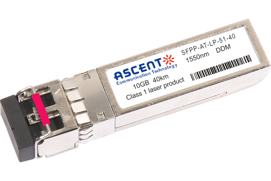
10G SFP+ ER 1550 nm 40 km
SFPP-ATLP-51-40 10 Gb/s 1550 nm SFP+ 40 km Transceiver
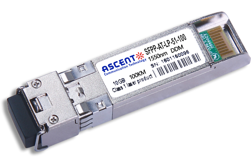
10G SFP+ CDR 1550 nm 100 km
SFPP-ATLP-51-100 10 Gb/s 1550 nm SFP+ 100 km Transceiver
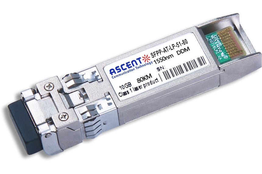
10G SFP+ ZR 1550 nm 80 km
SFPP-ATLP-51-80 10 Gb/s 1550 nm SFP+ 80 km Transceiver
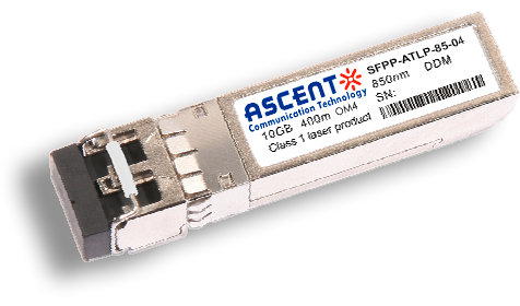
10G SFP+ 850 nm 400 m
10 Gb/s 850nm Multi-mode SFP+ Transceiver 400m
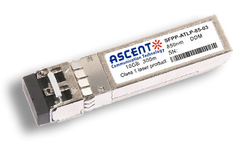
10G SFP+ 850 nm 300 m
SFPP-ATLP-85-03 10 Gb/s 850nm Multi-Mode SFP+ Transceiver
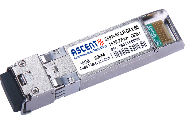
10G SFP+ DWDM 80 km
SFPP-ATLP-DXX-80 10 Gb/s DWDM SFP+ 80 km Transceiver
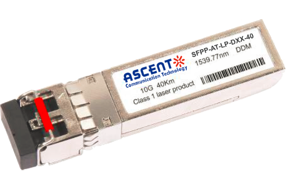
10G SFP+ DWDM 40 km
SFPP-ATLP-DXX-40 SFP+ Plug-in, 10Gbps, 40km, TX=ITU Ch xx (17 to 61) /RX wide, on two single mode fibers, LC/PC Blue
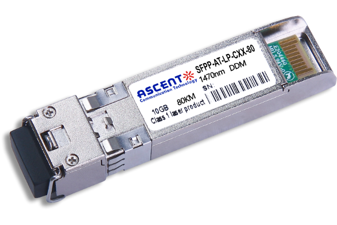
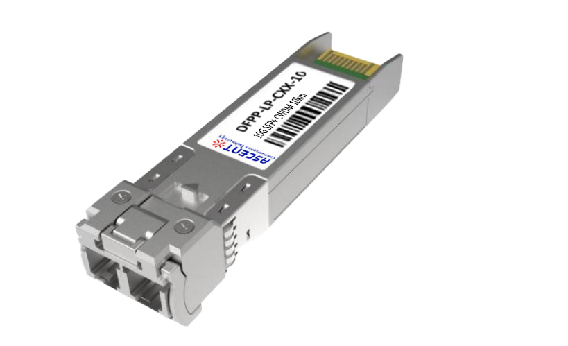
10G SFP+ CWDM 80 km
SFPP-ATLP-CXX-80 SFP+ Plug-in, 10 Gbps, 80 km, TX = CWDM Ch xx (1470ô nm to 1610 nm)/RX wide, on two single-mode fibers, LC/PC Blue.
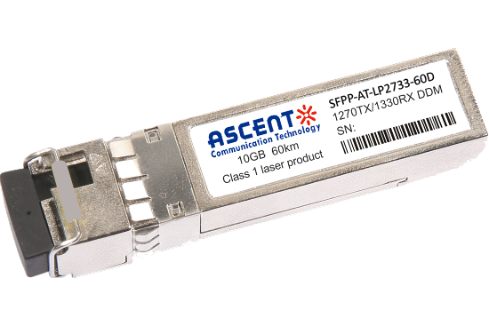
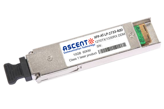
10G SFP+ CWDM 2733 60 km
SFPP-AT-LP-XXXX-60D 10 Gb/s BIDI SFP+ 60 km Transceiver
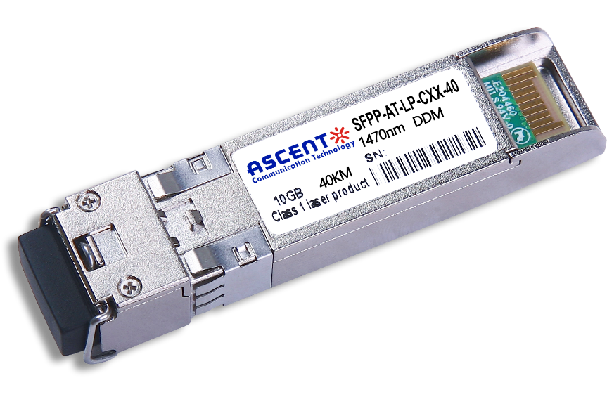
10G SFP+ CWDM 40 km
SFPP-ATLP-CXX-40 SFP+ Plug-in, 10Gbps, 40km, TX=CWDM Ch xx (1270ô nm to 1610 nm) /RX wide, on two single mode fibers, LC/PC Blue
10G SFP+ CWDM 10 km
10 Gb/s CWDM SFP+ 10 km Transceiver
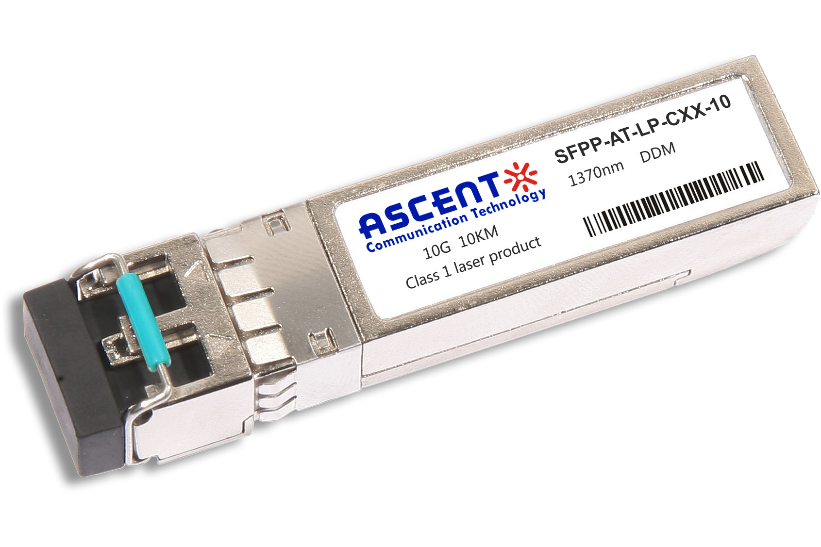
10G SFP+ Single mode CWDM 10 km
SFPP-ATLP-CXX-10 SFP+ Plug-in, 10 Gbps, 10 km, TX=CWDM Ch xx (1270 nm to 1610 nm)/RX wide, on two single-mode fibers, LC/PC Blue
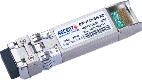
10G SFP+ CWDM 4955 80 km
SFP+ BIDI 10 Gb/s 1490/1550 nm 80 km Transceiver
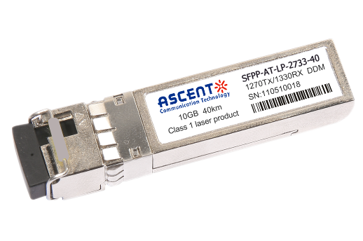
10G SFP+ CWDM 2733 40 km
SFPP-AT-LP-XXXX-40 SFP+ Plug-in, 10Gbps, 40km, TX=1270/RX=1330 , on one single mode fibers, LC/PC Blue
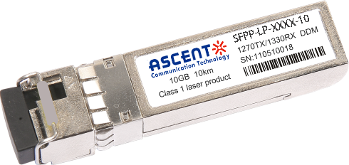
10G SFP+ CWDM 2733 10 km
SFPP-LP-XXXX-10 SFP+ Plug-in, 10Gbps, 10km, TX=1270/RX=1330 , on one single mode fibers, LC/PC Blue

10G XFP BIDI 80KM
XFP 10 Gb/s BIDI Single-Mode 80 km Transceiver DDM

10G XFP BIDI 40KM
XFP 10 Gb/s BIDI Single-Mode 40 km Transceiver DDM

10G XFP BIDI 20KM
XFP 10 Gb/s BIDI Single-Mode 20 km Transceiver DDM

10G XFP BIDI 10KM
XFP 10 Gb/s BIDI Single-Mode 10 km Transceiver DDM

10G XFP LR 1310 nm 20 km
XFP-AT-LP-31-20 10 Gb/s 20 km XFP Transceiver

10G XFP LR 1310 nm 10 km
XFP-AT-LP-31-10 10 Gb/s 10 km XFP Transceiver
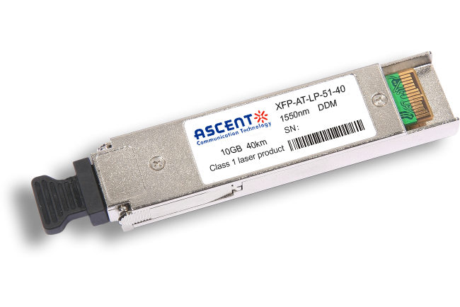
10G XFP ER 1550 nm 40 km
XFP-AT-LP-51-40 10 Gb/s 40 km XFP Optical Transceiver

10G XFP ZR 1550 nm 80 km
XFP-AT-LP-51-80 10 Gb/s 80 km XFP Optical Transceiver
10G XFP CWDM 2633 60 km
XFP-ATLP-XXXX-60 10 Gb/s BIDI XFP 60 km Transceiver
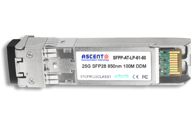
10G SFP+ CWDM 1610 80 km
SFPP-ATLP-61-80 SFP+ Plug-in, 10Gbps, 80km, TX=1610/RX wide, on two single mode fibers, LC/PC Blue
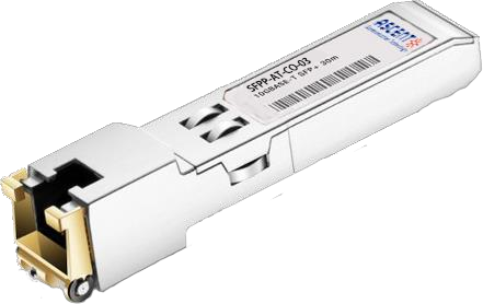
10G SFP+ Copper RJ45 30 m
SFPP-AT-CO-03 10GBASE-T SFP+ Copper RJ45 30m Transceiver

10G X2 850nm 300m
X2 10Gb/s 850nm Multi-mode Transceiver 300m
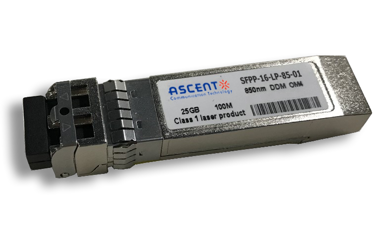
16G SFP+ FC 850 nm 100 m
SFPP-16-LP-85-01 16 Gb/s 850 nm SFP+ 100 m Transceiver
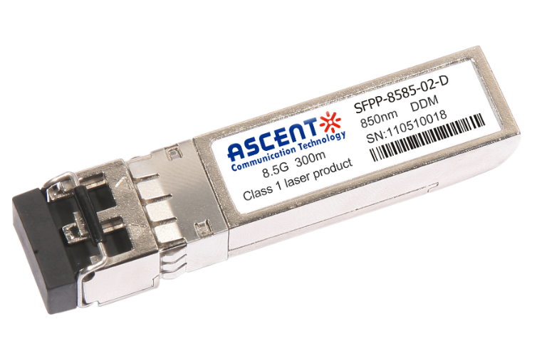
8.5G SFP+ SR 850 nm 150 m
SFPP-A8LP-85-015 8.5 Gb/s 850 nm Multi-Mode SFP+ Transceiver
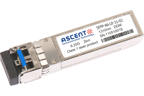
6.25G SFP+ LRM 1330 nm 2 km
SFPP-A6-LP-31-02 6.25 Gb/s Single-Mode SFP+ Transceiver
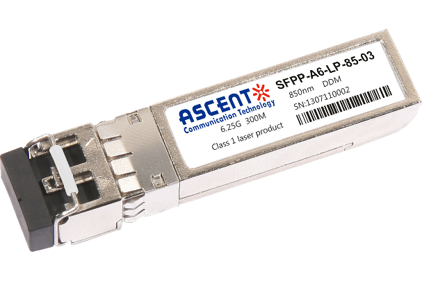
6.25G SFP+ SR 850 nm 300 m
SFPP-A6-LP-85-03 6.25 Gb/s 850 nm Multi-Mode SFP+ Transceiver
White Paper
Press Releases
Briefings 1
Briefings 2
Videos, etc.
QRG
Manual1
Manual2
Get in touch with our experts
Feedback