- FIBER OPTIC TRANSCEIVERS >800G & 400G Transceivers >10 Gb/s BIDI SFP+ Transceiver 20 km
10 Gb/s BIDI SFP+ Transceiver 20 km
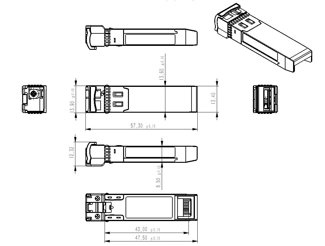
Ascent’s SFPP-LP-XXXX-20 transceivers are designed expressly for high-speed communication applications that require rates up to 11.3 Gb/s. They are designed to be compliant with the SFF-8472 SFP+ MSA. The module is suitable for data links up to 20 km in distance over a 9/125 µm single mode fiber. ASCENT SFP+ transceivers provide a unique enhanced digital diagnostic monitoring interface which allows real-time access to device operating parameters such as transceiver temperature, laser bias current, transmitted optical power, received optical power, and transceiver supply voltage. It also defines a sophisticated system of alarm and warning flags which alerts end users when particular operating parameters are outside of a factory set normal range.
§ Up to 11.3 Gb/s data links
§ Hot-Pluggable SFP Footprint and Single LC Connector
§ Up to 20 km reach for G.652 SMF
§ Compliant with SFF-8431, SFF-8432, SFF-8472 and IEEE802.3ae
§ Support data rate up to 11.3Gb/s
§ Hot-Pluggable SFP Footprint and Single LC Connector
§ Up to 20km reach for G.652 SMF
§ 1270nm DFB Transmitter and PIN receiver for SFPP-LP-2733-20
§ 1330nm DFB Transmitter and PIN receiver for SFPP-LP-3327-20
§ Temperature Range:
Commercial:0°C ~ +70°C
Industrial:-40°C ~ +85°C
§ Temperature Range:Compliant with SFF-8431
§ Compliant with SFF-8432
§ Compliant with SFF-8472
§ Compliant with IEEE802.3ae
Specifications
Absolute Maximum Ratings
Parameter | Symbol | Min. | Typ. | Max. | Unit | Note |
Storage Temperature | TS | -40 | +85 | °C | ||
Maximum Supply Voltage | VCC | -0.5 | 3.6 | V | ||
Operating Relative Humidity | RH | 95 | % |
Recommended Operating Conditions
Parameter | Symbol | Min. | Typ. | Max. | Unit | Note | |
Operating Case Temperature | Top | 0 | - | 70 | °C | Commercial | |
Top | -40 | - | 85 | °C | Industrial | ||
Power Supply Voltage | VCC | 3.13 | 3.3 | 3.47 | V | ||
Data Rate | BR | - | 10.3125 | 11.3 | Gbps | ||
Transmission Distance | TD | - | - | 20 | km | ||
Coupled Fiber | Single-mode fiber | 9/125 µm SMF | |||||
Optical Characteristics
Parameter | Symbol | Min. | Typ. | Max. | Unit | Note |
Data Rate | 10.3125 | 11.3 | Gbps | |||
Transmitter | ||||||
Center Wavelength Range | λC | 1260 | 1270 | 1280 | nm | SFPP-LP-2733-20 |
1320 | 1330 | 1340 | SFPP-LP-3327-20 | |||
Spectral Width (-20dB) | ∆λ | 1 | nm | |||
Side Mode Suppression Ratio | SMSR | 30 | dB | |||
Average Output Power | Pout | -6 | -1 | dBm | 1 | |
Extinction Ratio | ER | 3.5 | dB | |||
Average Power of OFF Transmitter | Poff | -30 | dBm | |||
Relative Intensity Noise | RIN | -128 | dB/Hz | 2 | ||
Receiver | ||||||
Wavelength Range | λC | 1320 | 1330 | 1340 | nm | SFPP-LP-2733-20 |
1260 | 1270 | 1280 | nm | SFPP-LP-3327-20 | ||
Receiver Sensitivity | Pmin | -14.4 | dBm | 3 | ||
Receiver Overload | Pmax | 0.5 | dBm | |||
LOS De-Assert | LOSD | -18 | dBm | |||
LOS Assert | LOSA | -30 | dBm | |||
LOS-Hysteresis | Phys | 0.5 | 6 | dB |
Notes:
1. Output is coupled into a 9/125um SMF.
2. 12dB reflection.
3. Measured with worst ER, BER less than 1E-12 and PRBS 231-1 at 10.3125Gbps.
Electrical Characteristics(TOP = Tc, Vcc = 3.135 to 3.465 Volts)
Parameter | Symbol | Min | Typ. | Max | Unit | Note |
Supply Voltage | Vcc | 3.135 | 3.465 | V | ||
Supply Current(Commercial) | Icc | 300 | mA | |||
Supply Current(Industrial) | Icc | 450 | mA | |||
Power Consumption(Commercial) | P | 1.0 | W | |||
Power Consumption(Industrial) | P | 1.5 | W | |||
Transmitter | ||||||
CML Inputs(Differential) | Vin | 150 | 1200 | mVpp | 1 | |
Input Impedance(Differential) | Zin | 85 | 100 | 115 | ohm | |
TX_DIS Disable | 2 | Vcc+0.3 | V | |||
TX_DIS Enable | 0 | 0.8 | V | |||
TX_FAULT Fault | 2 | Vcc+0.3 | V | |||
TX_FAULT Normal | 0 | 0.5 | V | |||
Receiver | ||||||
CML Outputs (Differential) | Vout | 350 | 700 | mVpp | 1 | |
Output Impedance (Differential) | Zout | 85 | 100 | 115 | Ohm | |
RX_LOS LOS | 2 | Vcc+0.3 | V | 2 | ||
RX_LOS Normal | 0 | 0.8 | V | 2 | ||
MOD_DEF (0:2) VoH | 2.5 | V | With Serial ID | |||
MOD_DEF (0:2) VoL | 0 | 0.5 | V | With Serial ID |
Note:
1. CML logic, internally AC coupled.
2. Loss Of Signal is LVTTL. Logic 0 indicates normal operation; logic 1 indicates no signal detected.
Timing Characteristics
Parameter | Symbol | Min | Typ. | Max | Unit | Note |
TX_Disable Assert Time | t_off | 100 | us | |||
TX_Disable Negate Time | t_on | 2 | ms | |||
Time to Initialize Include Reset of TX_FAULT | t_int | 300 | ms | |||
TX_FAULT from Fault to Assertion | t_fault | 100 | us | |||
TX_Disable Time to Start Reset | t_reset | 10 | us | |||
Receiver Loss of Signal Assert Time | TA,RX_LOS | 100 | us | |||
Receiver Loss of Signal Deassert Time | Td,RX_LOS | 100 | us | |||
Rate-Select Chage Time | t_ratesel | 10 | us | |||
Serial ID Clock Time | t_serial-clock | 100 | kHz |
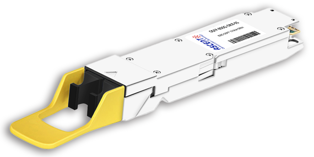
800G OSFP DR8 1310 nm 500 m
800 Gb/s DR8 OSFP 500m Optical Transceiver
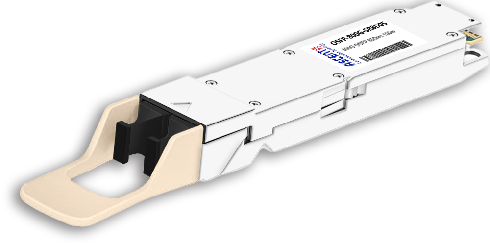
800G OSFP SR8 850 nm 100 m
OSFP-800G-SR8D-01 800 Gb/s OSFP SR8 850 nm 100 m Transceiver
400G QSFP56-DD 10km
400G QSFP-DD 4X100G LR1 Optical Transceiver
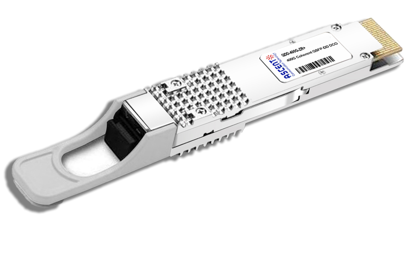
400G QSFP-DD ZR+
QSFP-DD-ZR-80 400 Gb/s QSFP-DD 80 km Transceiver
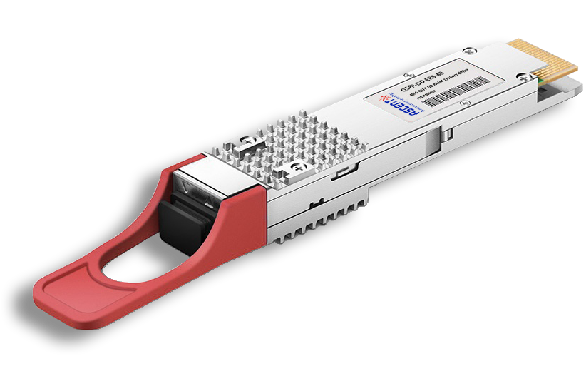
400G QSFP-DD ER8 40 km
QSFP-DD-ER8-40 400 Gb/s QSFP-DD 40 km Transceiver
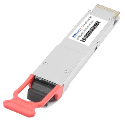
400G QSFP-DD 30 km
400 Gb/s QSFP-DD 30 km Transceiver
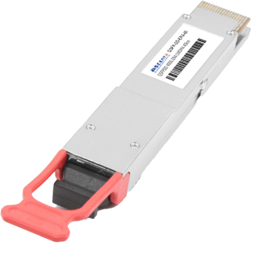
400G QSFP-DD 40 km
400 Gb/s QSFP-DD 40 km Transceiver
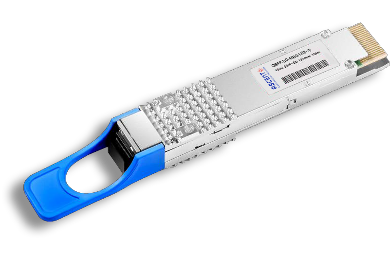
400G QSFP-DD LR8 1310 nm 10 km
QSFP-DD-LR8-10 400 Gb/s QSFP-DD LR8 10 km Transceiver

400G QSFP-DD LR4 CWDM 10 km
QSFP-DD-LR4-10 400 Gb/s QSFP-DD LR4 CWDM 10 km Transceiver
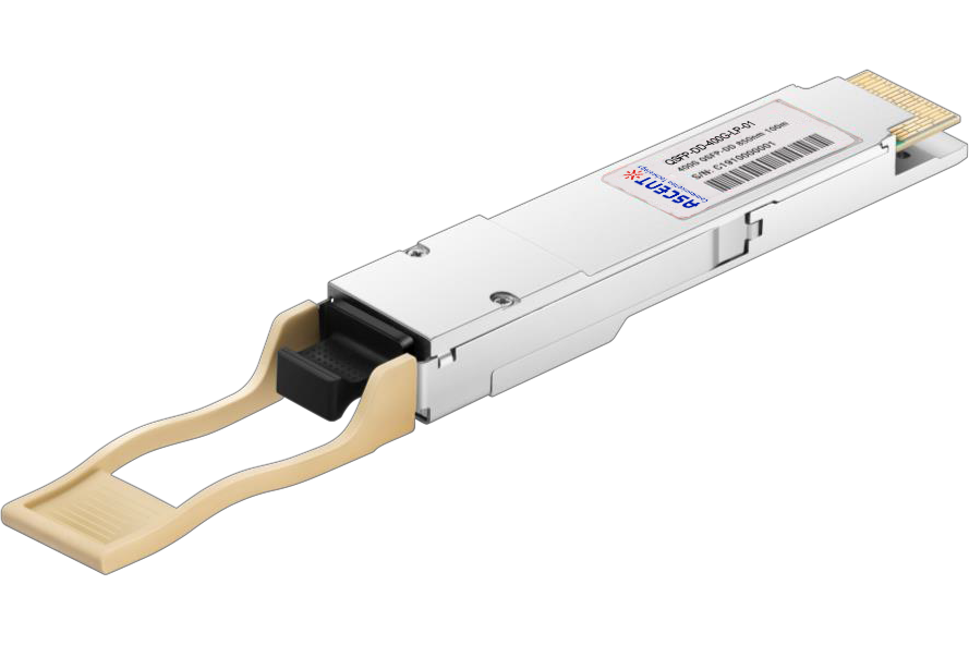
400G QSFP-DD SR8 850 nm 100 m
QSFP-DD-LP-01 400 Gb/s QSFP-DD SR8 100 m Transceiver
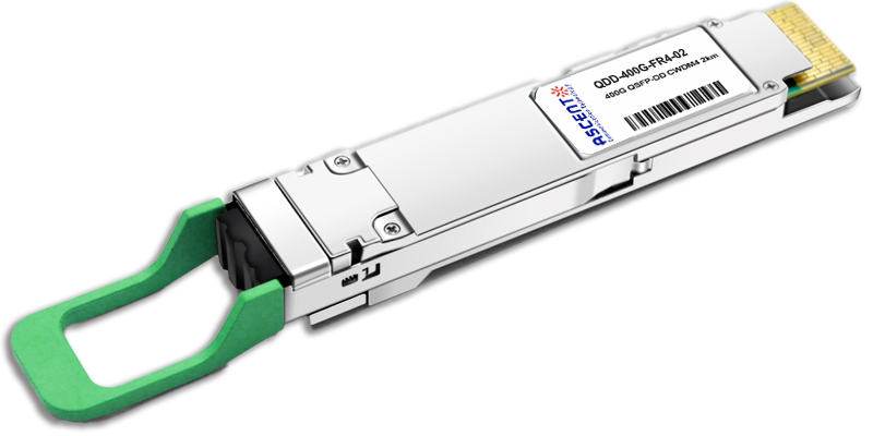
400G QSFP-DD FR4 2km
400 Gb/s QSFP-DD FR4 2 km DDM Transceiver
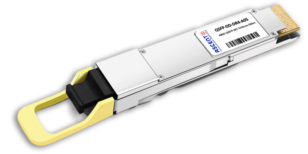
400G QSFP-DD DR4 500m
400 Gb/s QSFP-DD DR4 500m Transceiver
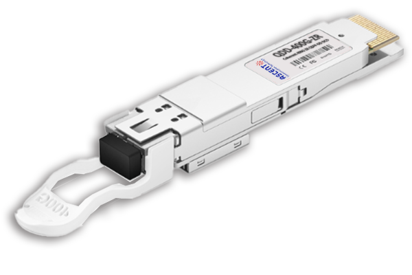
400G QSFP-DD DCO ZR
400G QSFP-DD DCO ZR Coherent Optical Transceiver
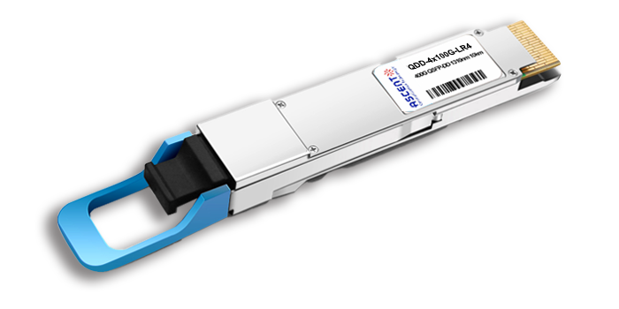
4X100G QSFP-DD LR4 10km
QDD 4x100G 1310nm LR 10 km Transceiver
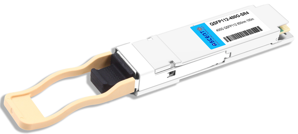
400G QSFP112 SR4 850 nm 100 m
QSFP112-400G-SR4-01 400 Gb/s QSFP112 SR4 850 nm 100 m Transceiver
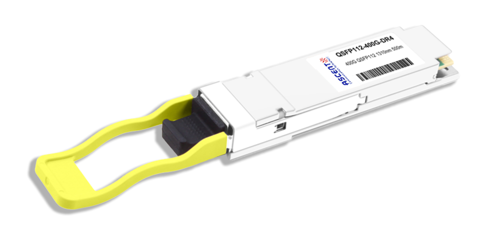
400G QSFP112 DR4 1310 nm 500 m
400G QSFP112 DR4 1310 nm Transceiver 500m
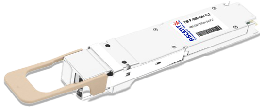
400G OSFP SR4 FLT 50m Transceiver
400 Gbps Multi-Mode 50m OSFP Transceiver
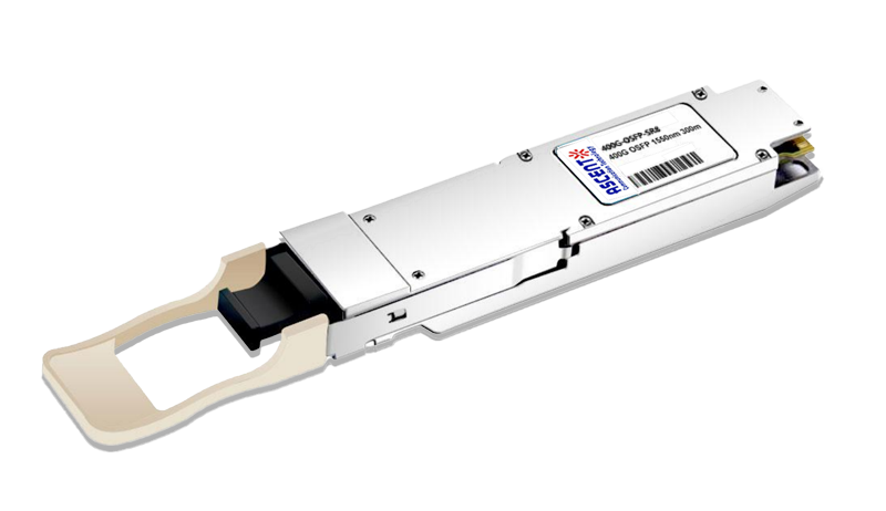
400G OSFP SR8 100m Transceiver
400 Gbps PSM8 Multi-Mode 100m OSFP Transceiver
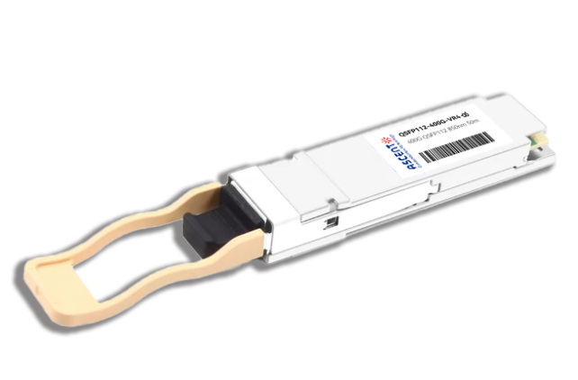
400G QSFP112 VR4 Transceiver
400G QSFP112 VR4
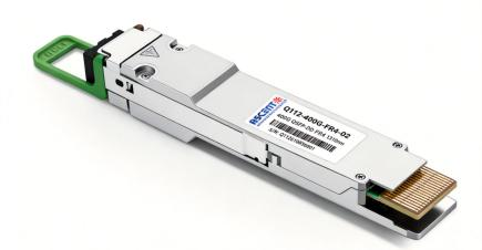
400G QSFP 112 FR4 2km Transceiver
Q112-400G-FR4-02
White Paper
Press Releases
Briefings 1
Briefings 2
Videos, etc.
QRG
Manual1
Manual2
Get in touch with our experts
Feedback