- FIBER OPTIC TRANSCEIVERS >10G Transceivers >10G SFP+ ZR 1550 nm 80 km
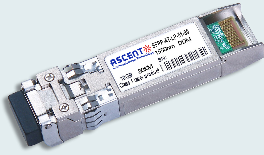
10G SFP+ ZR 1550 nm 80 km
ASCENTãs SFP+ transceiver SFPP-ATLP-51-80 is designed for use in 10-Gigabit Ethernet links up to 80 km over single mode fiber.
ã Up to 11.1 Gbps Data Links
ã Up to 80 km transmission on SMF
ã EML transmitter and PIN receiver
ã Metal enclosure, for lower EMI
ã 2-wire interface with integrated Digital Diagnostic monitoring
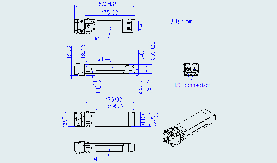
ã Hot-pluggable SFP+ footprint
ã Compliant with SFP+ MSA with LC connector
ã Compliant with SFF-8472
ã Compliant with SFF-8431
ã Single 3.3V power supply
ã Case operating temperature range: 0 ô¯C to 70 ô¯C
ã Power dissipation < 1.5 W
ã Compliant with IEEE802.3ae, 10BASE-ZR/ZW
ã RoHS compliant
Absolute Maximum Ratings
Parameter | Symbol | Min. | Typ. | Max. | Unit | Note |
Storage Temperature | Ts | ã40 | ã | 85 | ô¯C | |
Relative Humidity | RH | 5 | ã | 95 | % | |
Power Supply Voltage | VCC | ã0.3 | ã | 4 | V | |
Signal Input Voltage | Vccã0.3 | ã | Vcc+0.3 | V |
Recommended Operating Conditions
Parameter | Symbol | Min. | Typ. | Max. | Unit | Note |
Operating Case Temperature | Tcase | 0 | ã | +70 | ô¯C | Commercial |
ã40 | ã | +85 | ô¯C | Industrial | ||
Power Supply Voltage | VCC | 3.14 | 3.3 | 3.47 | V | |
Power Supply Current | ICC | ã | 450 | mA | ||
Data Rate | BR | 10.3125 | Gbps | |||
Transmission Distance | TD | ã | 80 | km | ||
Coupled fiber | Singleãmode fiber | 9/125 ôçm SMF | ||||
Optical Characteristics
Parameter | Symbol | Min. | Typ. | Max. | Unit | Note |
Transmitter | ||||||
Average Launched Power | PO | ã1 | +4 | dBm | 1 | |
Extinction Ratio | ER | 8.2 | dB | |||
Center Wavelength | ö£c | 1530 | 1550 | 1565 | nm | |
Spectrum Band Width (RMS) | ü | 1.0 | nm | |||
SMSR | 30 | dB | ||||
Transmitter OFF Output Power | POff | ã30 | dBm | |||
Transmitter and Dispersion Penalty | TDP | 3.0 | dB | |||
Output Eye Mask | Compliant with IEEE 802.3ae | |||||
Receiver | ||||||
Input Optical Wavelength | ö£ | 1270 | 1610 | nm | ||
Receiver Sensitivity | Psen | ã23 | dBm | 2 | ||
Input Saturation Power (Overload) | Psat | ã6 | dBm | |||
Receiver Reflectance | Rrx | ã27 | dB | |||
LOS Assert | LOSA | ã35 | dBm | |||
LOS DeãAssert | LOSD | ã26 | dBm | |||
LOS Detect Hysteresis | PHYS | 0.5 | dB | |||
Note:
1. Launched power (avg.) is power coupled into a singleãmode fiber with master connector. (Before of Life)
2. Measured with conformance test signal for BER = 10ã12 @ 10.3125 Gbps, PRBS=231ã1, NRZ.
Electrical Characteristics
Parameter | Symbol | Min | Typ | Max | Unit | Note |
Supply Voltage | Vcc | 3.14 | 3.3 | 3.46 | V | |
Supply Current | Icc | 450 | mA | Commercial | ||
550 | mA | Industrial | ||||
Transmitter | ||||||
Input Differential Impedance | Rin | 100 | öˋ | 1 | ||
Single Ended Data Input Swing | Vin, pp | 180 | 700 | mV | ||
Transmit Disable Voltage | VD | Vccã1.3 | Vcc | V | ||
Transmit Enable Voltage | VEN | Vee | Vee+ 0.8 | V | 2 | |
Transmit Disable Assert Time | 10 | ôçs | ||||
Receiver | ||||||
Differential data output swing | Vout, pp | 300 | 850 | mV | 3 | |
Data output rise time | tr | 28 | ps | 4 | ||
Data output fall time | tf | 28 | ps | 4 | ||
LOS Fault | VLOS fault | Vccã1.3 | VccHOST | V | 5 | |
LOS Normal | VLOS norm | Vee | Vee+0.8 | V | 5 | |
Power Supply Rejection | PSR | 100 | mVpp | 6 |
Notes:
1. Connected directly to TX data input pins. AC coupled thereafter.
2. Or open circuit.
3. Into 100 öˋ differential termination.
4. 20 % to 80 %.
5. Loss Of Signal is LVTTL. Logic 0 indicates normal operation; logic 1 indicates no signal detected.
6. Receiver sensitivity is compliant with power supply sinusoidal modulation of 20 Hz to 1.5 MHz up to specified value applied through the recommended power supply filtering network.
Regulatory Compliance
Feature | Reference | Performance |
Electrostatic Discharge (ESD) | IEC/EN 61000ã4ã2 | Compatible with standards |
Electromagnetic Interference (EMI) | FCC Part 15 Class B EN 55022 Class B (CISPR 22A) | Compatible with standards |
Laser Eye Safety | FDA 21CFR 1040.10, 1040.11 IEC/EN 60825ã1, 2 | Class 1 laser product |
Component Recognition | IEC/EN 60950, UL | Compatible with standards |
ROHS | 2002/95/EC | Compatible with standards |
EMC | EN61000ã3 | Compatible with standards |

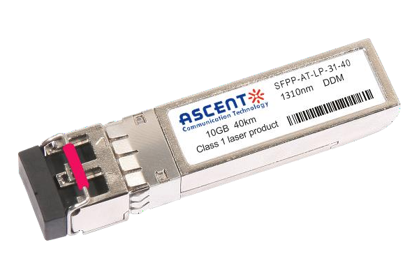
10G SFP+ LR 1310 nm 40 km
10 Gb/s 1310nm SFP+ 40 km Transceiver

10G SFP+ LR 1310 nm 20 km
SFPP-ATLP-31-20 SFP+ Plug-in, 10Gbps, 20km, TX=1310/RX wide, on two single mode fibers, LC/PC Blue
10G SFP+ LR 1310 nm 10 km
SFPP-ATLP-31-10 SFP+ Plug-in, 10Gbps, 10km, TX=1310/RX wide, on two single mode fibers, LC/PC Blue

10G SFP+ LRM 1310 nm 2 km
SFPP-ATLP-31-02 10Gb/s 1310nm SFP+ 2 km Transceiver
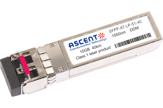
10G SFP+ ER 1550 nm 40 km
SFPP-ATLP-51-40 10 Gb/s 1550 nm SFP+ 40 km Transceiver
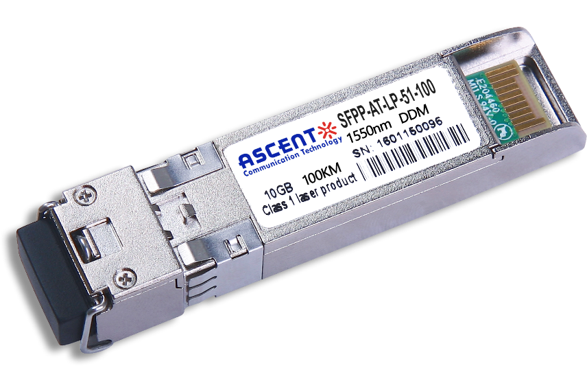
10G SFP+ CDR 1550 nm 100 km
SFPP-ATLP-51-100 10 Gb/s 1550 nm SFP+ 100 km Transceiver
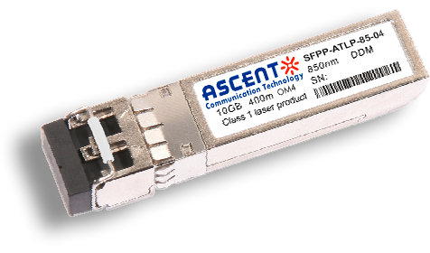
10G SFP+ 850 nm 400 m
10 Gb/s 850nm Multi-mode SFP+ Transceiver 400m
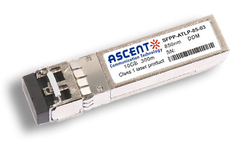
10G SFP+ 850 nm 300 m
SFPP-ATLP-85-03 10 Gb/s 850nm Multi-Mode SFP+ Transceiver
10G SFP+ Tunable DWDM 80 km
SFPP-LP-T99R-80 10 Gb/s Tunable DWDM SFP+ 80 km Transceiver
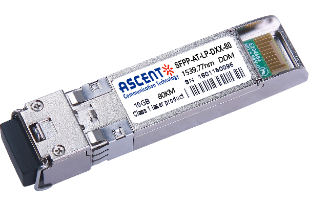
10G SFP+ DWDM 80 km
SFPP-ATLP-DXX-80 10 Gb/s DWDM SFP+ 80 km Transceiver
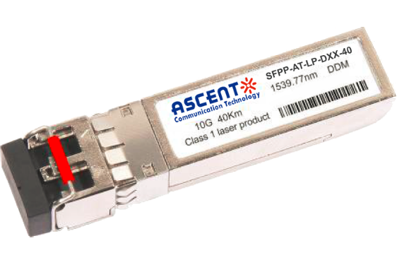
10G SFP+ DWDM 40 km
SFPP-ATLP-DXX-40 SFP+ Plug-in, 10Gbps, 40km, TX=ITU Ch xx (17 to 61) /RX wide, on two single mode fibers, LC/PC Blue
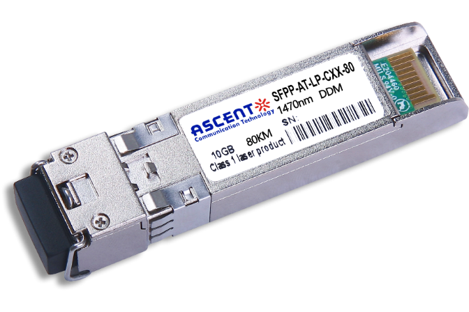
10G SFP+ CWDM 80 km
SFPP-ATLP-CXX-80 SFP+ Plug-in, 10 Gbps, 80 km, TX = CWDM Ch xx (1470ô nm to 1610 nm)/RX wide, on two single-mode fibers, LC/PC Blue.
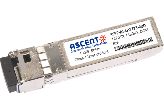
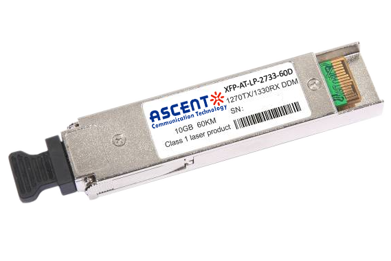
10G SFP+ CWDM 2733 60 km
SFPP-AT-LP-XXXX-60D 10 Gb/s BIDI SFP+ 60 km Transceiver
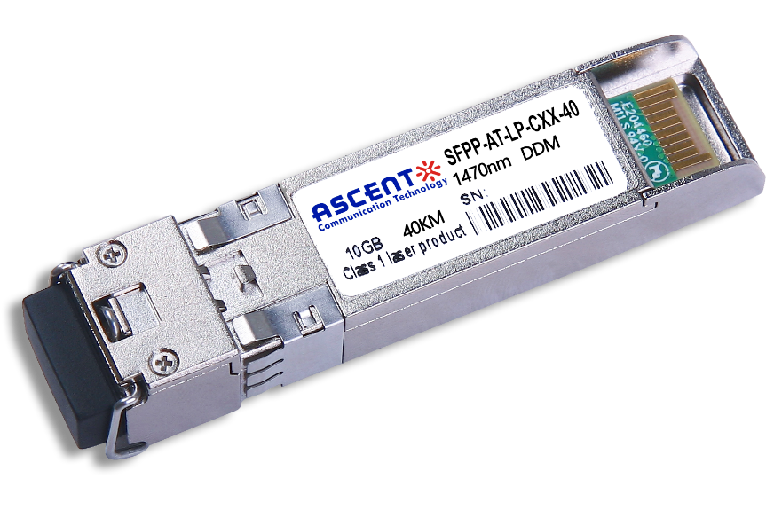
10G SFP+ CWDM 40 km
SFPP-ATLP-CXX-40 SFP+ Plug-in, 10Gbps, 40km, TX=CWDM Ch xx (1270ô nm to 1610 nm) /RX wide, on two single mode fibers, LC/PC Blue
10G SFP+ CWDM 10 km
10 Gb/s CWDM SFP+ 10 km Transceiver
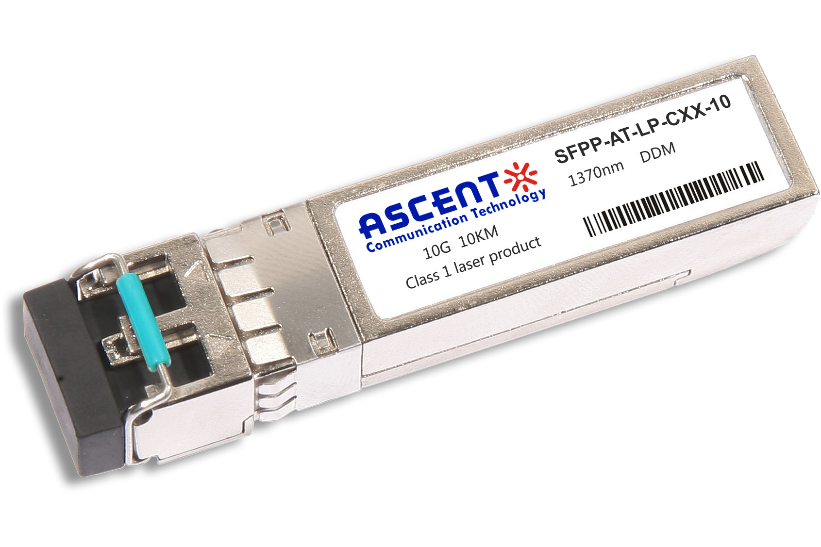
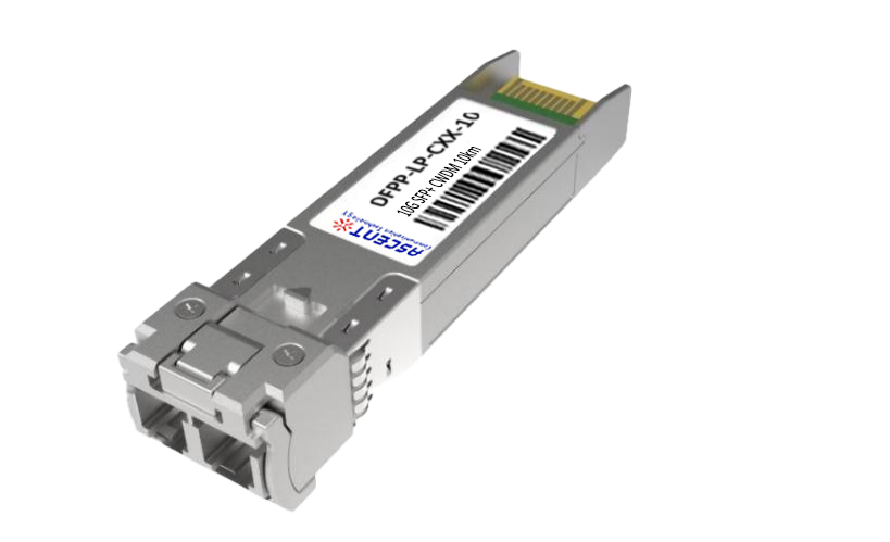
10G SFP+ Single mode CWDM 10 km
SFPP-ATLP-CXX-10 SFP+ Plug-in, 10 Gbps, 10 km, TX=CWDM Ch xx (1270 nm to 1610 nm)/RX wide, on two single-mode fibers, LC/PC Blue
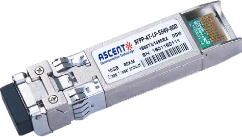
10G SFP+ CWDM 4955 80 km
SFP+ BIDI 10 Gb/s 1490/1550 nm 80 km Transceiver
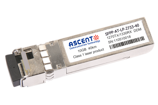
10G SFP+ CWDM 2733 40 km
SFPP-AT-LP-XXXX-40 SFP+ Plug-in, 10Gbps, 40km, TX=1270/RX=1330 , on one single mode fibers, LC/PC Blue
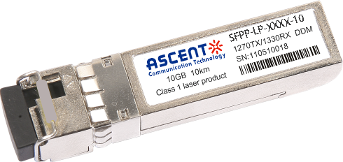
10G SFP+ CWDM 2733 10 km
SFPP-LP-XXXX-10 SFP+ Plug-in, 10Gbps, 10km, TX=1270/RX=1330 , on one single mode fibers, LC/PC Blue

10G XFP BIDI 80KM
XFP 10 Gb/s BIDI Single-Mode 80 km Transceiver DDM

10G XFP BIDI 40KM
XFP 10 Gb/s BIDI Single-Mode 40 km Transceiver DDM

10G XFP BIDI 20KM
XFP 10 Gb/s BIDI Single-Mode 20 km Transceiver DDM

10G XFP BIDI 10KM
XFP 10 Gb/s BIDI Single-Mode 10 km Transceiver DDM

10G XFP LR 1310 nm 20 km
XFP-AT-LP-31-20 10 Gb/s 20 km XFP Transceiver

10G XFP LR 1310 nm 10 km
XFP-AT-LP-31-10 10 Gb/s 10 km XFP Transceiver
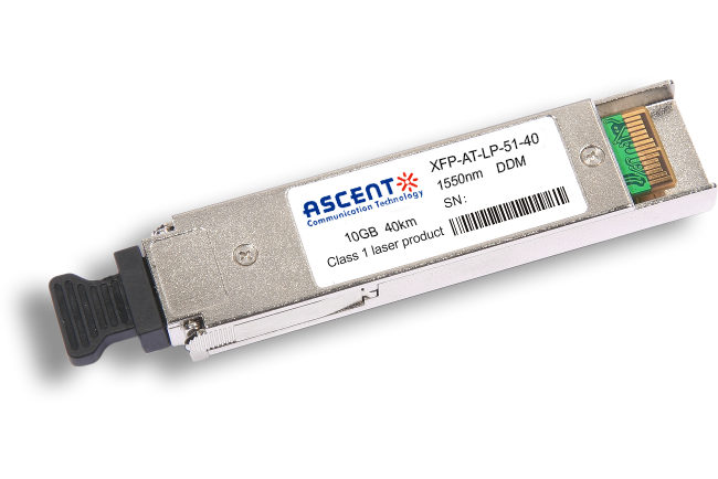
10G XFP ER 1550 nm 40 km
XFP-AT-LP-51-40 10 Gb/s 40 km XFP Optical Transceiver

10G XFP ZR 1550 nm 80 km
XFP-AT-LP-51-80 10 Gb/s 80 km XFP Optical Transceiver
10G XFP CWDM 2633 60 km
XFP-ATLP-XXXX-60 10 Gb/s BIDI XFP 60 km Transceiver
10G SFP+ CWDM 1610 80 km
SFPP-ATLP-61-80 SFP+ Plug-in, 10Gbps, 80km, TX=1610/RX wide, on two single mode fibers, LC/PC Blue
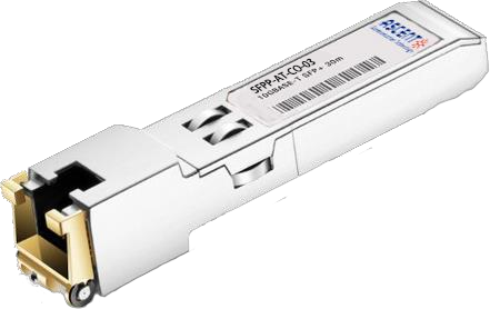
10G SFP+ Copper RJ45 30 m
SFPP-AT-CO-03 10GBASE-T SFP+ Copper RJ45 30m Transceiver

10G X2 850nm 300m
X2 10Gb/s 850nm Multi-mode Transceiver 300m
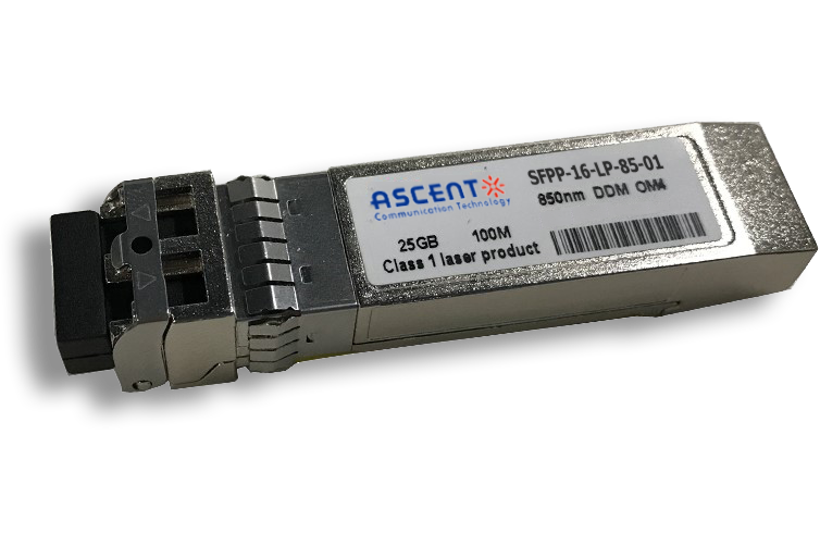
16G SFP+ FC 850 nm 100 m
SFPP-16-LP-85-01 16 Gb/s 850 nm SFP+ 100 m Transceiver
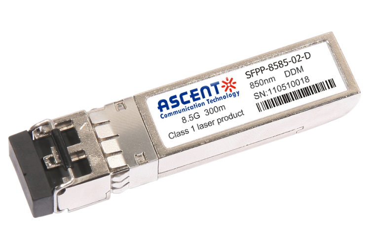
8.5G SFP+ SR 850 nm 150 m
SFPP-A8LP-85-015 8.5 Gb/s 850 nm Multi-Mode SFP+ Transceiver
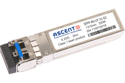
6.25G SFP+ LRM 1330 nm 2 km
SFPP-A6-LP-31-02 6.25 Gb/s Single-Mode SFP+ Transceiver
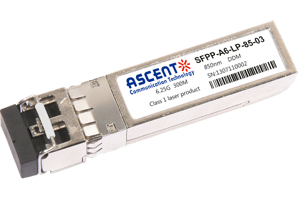
6.25G SFP+ SR 850 nm 300 m
SFPP-A6-LP-85-03 6.25 Gb/s 850 nm Multi-Mode SFP+ Transceiver
White Paper
Press Releases
Briefings 1
Briefings 2
Videos, etc.
Manual1
Manual2
Get in touch with our experts
Feedback