- FIBER OPTIC TRANSCEIVERS >40G & 25G Transceivers >64G SFP56 850nm 100m

64G SFP56 850nm 100m
The 64GBASE-SW SFP56 Optical Transceiver Module is a high-performance solution designed for short-reach fiber communication applications. Operating over multimode fiber (MMF) at an 850 nm wavelength, it supports data rates up to 64G and link distances of up to 100 meters. With its compact SFP56 form factor and LC duplex connector, the module provides a reliable, space-efficient interface for high-speed data transmission. Fully compliant with industry standards including SFF-8472, SFF-8431, SFF-8432, and FC-PI-8, this transceiver ensures seamless interoperability with a wide range of networking equipment. It features Digital Optical Monitoring (DOM) functions accessible via a 2-wire management interface, enabling real-time monitoring of critical operating parameters such as optical power, voltage, and temperature. These advanced diagnostics enhance system management, fault detection, and long-term reliability. Engineered for ease of use, the module is hot-swappable, allowing quick installation and replacement without disrupting network operations. Its blend of performance, compatibility, and flexibility makes it ideal for data centers, enterprise networks, and high-bandwidth storage environments where efficient short-distance connectivity is essential. With robust compliance and monitoring features, the 64GBASE-SW SFP56 transceiver delivers dependable high-speed optical performance in demanding environments.
ôñ Supports 16GFC/32GFC/64GFC data rates
ôñ Up to 100m transmission on multi-mode fiber
ôñ VCSEL laser and PIN receiver
ôñ 2-wire interface with integrated Digital Diagnostic Monitoring
ôñ Hot-pluggable SFP footprint
ôñ Compliant with SFP MSA with LC connector
ôñ Single 3.3V power supply
ôñ Power consumption < 1.5W
ôñ Case operating temperature range: 0ô¯C to 70ô¯C
Absolute Maximum Ratings
Parameter | Symbol | Min. | Typ. | Max. | Unit |
Storage Temperature | Ts | -40 | 85 | ô¯C | |
Relative Humidity | RH | 0 | 85 | % | |
Power Supply Voltage | VCC | -0.3 | 3.63 | V |
Recommended Operating Conditions
Parameter | Min. | Typ. | Max. | Unit | Notes |
Case Operating Temperature | 0 | 70 | ô¯C | ||
Power Supply Voltage | 3.135 | 3.3 | 3.45 | V | |
Power Supply Current | mA | ||||
64GFC Signaling Rate | 28.9 | GBd | GBd | ||
32GFC Signaling Rate | 28.05 | GBd | GBd | ||
16GFC Signaling Rate | 14.025 | GBd | GBd | ||
64GFC Transmission Distance | 70 (OM3) 100 (OM4/OM5) | m | |||
32GFC Transmission Distance | 20 (OM2) 70 (OM3) 100 (OM4) | m | |||
16GFC Transmission Distance | 35 (OM2) 100 (OM3) 125 (OM4) | m | |||
64GFC Bit Error Rate | 10-10 | 1.09x10⁻⁴ | 1 | ||
32GFC Bit Error Rate | 10-6 | 2 | |||
16GFC Bit Error Rate | 10-12 | 2 | |||
Coupled Fiber | Multi-mode fiber | 50/125um MMF | |||
Notes:
1. PRBS31Q for 64GFC.
2. PRBS31 for 32GFC/16GFC.
Optical Characteristics (64GFC Optical Parameters)
Parameter | Min. | Typ. | Max. | Unit | Notes |
Transmitter (Module Output) | |||||
Center Wavelength | 840 | 850 | 860 | nm | |
RMS Spectral Width | 0.6 | nm | |||
TDECQ | 5.5 | dB | |||
TDECQ-10log10(Ceq) | 5.5 | dB | |||
OMAouter | -4.5 | 3 | dBm | ||
OMAouter Extinction Ratio | 3 | dB | |||
Launched Power in OMAouter Minus TDECQ | -5.9 | dBm | |||
Average Launched Power | -7.5 | 0 | dBm | ||
RIN12 OMA | -128 | dB/Hz | |||
Transition Time 20%-80% | 34 | ps | |||
Encircled Flux | >86% at 19um, <30% at 4.5um | ||||
Receiver (Module Input) | |||||
Damage Threshold | 5 | dBm | 1 | ||
Average Received Power | -9.4 | 4 | dBm | ||
Receiver Power (OMAouter) | 3 | dBm | |||
Return Loss of Receiver | 12 | dB | |||
Receiver Sensitivity, OMAouter | -7 | dBm | |||
Stressed Receiver Sensitivity, OMAouter | -2.4 | dBm | |||
LOS De-Assert | -11 | dBm | |||
LOS Assert | -30 | -11 | dBm | ||
32GFC Optical Parameters
Parameter | Min. | Typ. | Max. | Unit | Notes |
Transmitter (Module Output) | |||||
Center Wavelength | 840 | 850 | 860 | nm | |
RMS Spectral Width | 0.570 | nm | |||
Average Launched Power | 0.240 (-6.2) | 1.585 (2) | mW (dBm) | ||
Optical Modulation Amplitude | 0.479 (-3.2) | mW (dBm) | |||
Vertical Eye Closure Penalty (VECPq) | 3.13 | dB | |||
RIN12 OMA | -129 | dB/Hz | |||
Encircled Flux | >86% at 19um, <30% at 4.5um | ||||
Receiver (Module Input) | |||||
Average Received Power | 1.585 (2) | mW (dBm) | |||
Unstressed Receiver Sensitivity, OMA | 0.095 (-10.2) | mW (dBm) | |||
Return Loss of Receiver | 12 | dB | |||
Rx Jitter Tracking Test, OMA | 0.295(-5.3) | mW(dBm) | |||
RX Jitter Tracking Test, Jitter Frequency and Pk-Pk Amplitude | (500,1) (100,5) | (kHz,UI) | |||
Receiver Electrical 3 dB Upper Cutoff Frequency | 32 | GHz | |||
Stressed Receiver Sensitivity, OMA | 0.263 (-5.8) | mW (dBm) | |||
LOS De-Assert | -11 | dBm | |||
LOS Assert | -30 | -11 | dBm | ||
16GFC Optical Parameters (Compliant with all other parameters in FC-PI-5)
Parameter | Min. | Typ. | Max. | Unit | Notes |
Transmitter (Module Output) | |||||
Center Wavelength | 840 | 850 | 860 | nm | |
RMS Spectral Width | 0.59 | nm | |||
Average Launched Power | -7.8 | 0 | dBm | 1 | |
Optical Modulation Amplitude | 0.331 (-4.8) | mW (dBm) | |||
Vertical Eye Closure Penalty (VECPq) | 2.56 | dB | |||
RIN12 OMA | -128 | dB/Hz | |||
Encircled Flux | >86% at 19um, <30% at 4.5um | ||||
Receiver (Module Input) | |||||
Average Received Power | 0 | dBm | |||
Unstressed Receiver Sensitivity, OMA | 0.089 (-10.5) | mW (dBm) | |||
Return Loss of Receiver | 12 | dB | |||
Rx Jitter Tolerance Test, OMA | 0.214(-6.7) | mW(dBm) | |||
RX Jitter Tracking Test, Jitter Frequency and Pk-Pk Amplitude | (840,1) (168,5) | (kHz,UI) | |||
Receiver Electrical 3dB Upper Cutoff Frequency | 18 | GHz | |||
Stressed Receiver Sensitivity, OMA | 0.170 (-7.7) | mW (dBm) | |||
LOS De-Assert | -11 | dBm | |||
LOS Assert | -30 | -11 | dBm | ||
Note: Max average launched power shall be the lesser of the value listed here or the Class 1 laser safety limits (CDRH and EN 60825).
Electrical Characteristics
Parameter | Symbol | Min. | Typ. | Max. | Unit | Notes |
Power Supply Voltage | Vcc | 3.135 | 3.3 | 3.465 | V | |
Power Supply Current | 454 | mA | ||||
Low Speed Signals | ||||||
Tx_Fault, Rx_LOS Output Voltage | VOL | -0.3 | 0.40 | V | At 0.7 mA | |
Tx_Disable, RS0, RS1 Input Voltage | VIL | -0.3 | 0.8 | V | ||
VIH | 2.0 | Vcc+0.3 | V |
64G Electrical Parameters
Parameter | Min. | Typ. | Max. | Unit | Notes |
Transmitter (Module Input) | |||||
Differential Input Voltage Tolerance | 900 | mV | |||
Differential Termination Resistance Mismatch | 10 | % | |||
Differential Return Loss SDD11 |  | dB | |||
Differential-Mode to Common Conversion SCD11 |  | dB | At 0.7 mA | ||
Input Equalization | -0.3 | 10 | dB | ||
Receiver (Module Output) | |||||
Differential Voltage, Pk-Pk | 900 | mV | |||
Differential Voltage with Transmitter Disabled, Pk-Pk | 35 | mV | |||
Common-Mode Noise Rms | 17.5 | mV | |||
Differential Termination Resistance Mismatch | 10 | % | At 1 MHz | ||
Differential Return Loss SDD22 |  | dB | |||
Common-Mode to Differential Conversion SDC22 |  | dB | |||
Source Transition Time 20% yto 80% | 9.5 | ps | |||
Eye Width at 10-5 Probability EW5 | 0.265 | UI | |||
Eye Height at 10-5 Probability EH5 | 70 | mV | |||
Vertical Eye Closure VEC | 12 | dB | |||
Output Emphasis | 5 | dB | |||
32G Electrical Parameters
Parameter | Min. | Typ. | Max. | Unit | Notes |
Transmitter (Module Input) | |||||
Differential Termination Resistance Mismatch | 10 | % | |||
Differential Return Loss SDD11 |  | % | |||
Common Mode to Differential Conversion SDC11 |  | dB | |||
Differential Mode to Common Conversion SCD11 |  | ||||
Input Equalization | 10 | dB | |||
Receiver (module output) | |||||
Differential Voltage, Pk-Pk | 900 | mV | |||
Common-Mode Noise Rms | 17.5 | mV | |||
Differential Termination Resistance Mismatch | 10 | % | At 1 MHz | ||
Differential Return Loss SDD22 |  | % | |||
Common Mode to Differential Conversion SDC22 |  | dB | |||
Differential Mode to Common Conversion SCD22 |  | dB | |||
Common Mode Return Loss SCC22 | -2 | dB | |||
Source Transition Time 20% to 80% | 9.5 | ps | |||
Vertical Eye Closure | 4 | dB | |||
Eye Width at 10-6 Probability EW6 | 0.65 | UI | |||
Eye Height at 10-6 Probability EH6 | 250 | mV | |||
Output Emphasis | 5 | dB | |||
16G Electrical Parameters (Compliant with all other parameters in FC-PI-5)
Parameter | Min. | Typ. | Max. | Unit | Notes |
Transmitter (Module Input) | |||||
Common Mode Voltage (rms) | 30 | mV | |||
Common Mode Voltage, (Spectral Peak)(rms) | 20 | mV | |||
Input Equalization | 10 | dB | |||
Receiver (module output) | |||||
Output Emphasis | 5 | dB | |||
Timing Requirement of Control and Status I/O
Parameter | Symbol | Min. | Max. | Unit. | Notes |
Tx_Disable Assert Time | t_off | ã | 100 | ö¥s | |
Tx_Disable Negate Time | t_on | ã | 2 | ms | |
Time to Initialize 2-Wire Interface | t_2w_start_up | ã | 800 | ms | |
Time to Initialize | t_start_up | ã | 2500 | ms | 1 |
Time to Power Up to Level II | t_power_level2 | ã | 1700 | ms | 1 |
Time to Power Down from Level II | t_power_down | ã | 1700 | ms | 1 |
Tx_Fault Assert | Tx_Fault_on | ã | 1 | ms | |
Tx_Fault Reset | t_reset | 10 | ã | ö¥s | |
RS0, RS1 Rate Select Timing for FC | t_RS0_FC,t_RS1_FC | ã | 4 | ms | |
Rx_LOS Assert Delay | t_los_on | ã | 7 | ms | |
Rx_LOS Negate Delay | t_los_off | ã | 7 | ms |
Regulatory Compliance
Feature | Reference | Performance |
Electrostatic discharge(ESD) | IEC/EN 61000-4-2 | Compatible with standards |
Electromagnetic Interference (EMI) | FCC Part 15 Class B EN 55022 Class B (CISPR 22A) | Compatible with standards |
Laser Eye Safety | FDA 21CFR 1040.10, 1040.11 IEC/EN 60825-1, 2 | Class 1 laser product |
Component Recognition | IEC/EN 60950, UL | Compatible with standards |
ROHS | 2011/65/EU and (EU)2015/863 | Compatible with standards |
EMC | EN61000-3 | Compatible with standards |

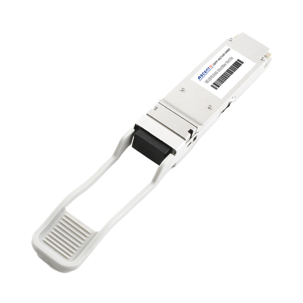
40/100G SFP28 SWDM4 100m
40/100Gb/s QSFP28, Bi-Di, Duplex LC 100m Transceiver

40G QSFP+ ER4 Industrial 40 km
40 Gb/s QSFP+ ER4 40 km Transceiver

40G QSFP+ ER4 40 km
40 Gb/s QSFP+ ER4 40 km Transceiver

40G QSFP+ LR4 Industrial 10 km
40 Gb/s QSFP+ LR4 10 km Transceiver

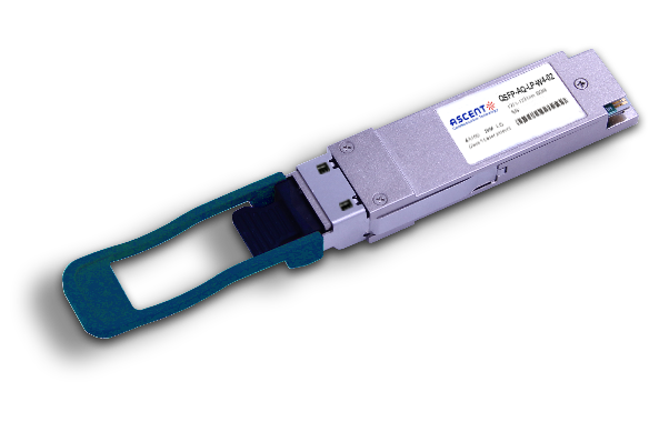
40G QSFP+ LR4 10 km
QSFP-AQ-LP-W4-10 40 Gb/s QSFP LR4 10 km Transceiver

40G QSFP+ PSM4 2 km
40 Gb/s QSFP+ PSM4 Transceiver 2km
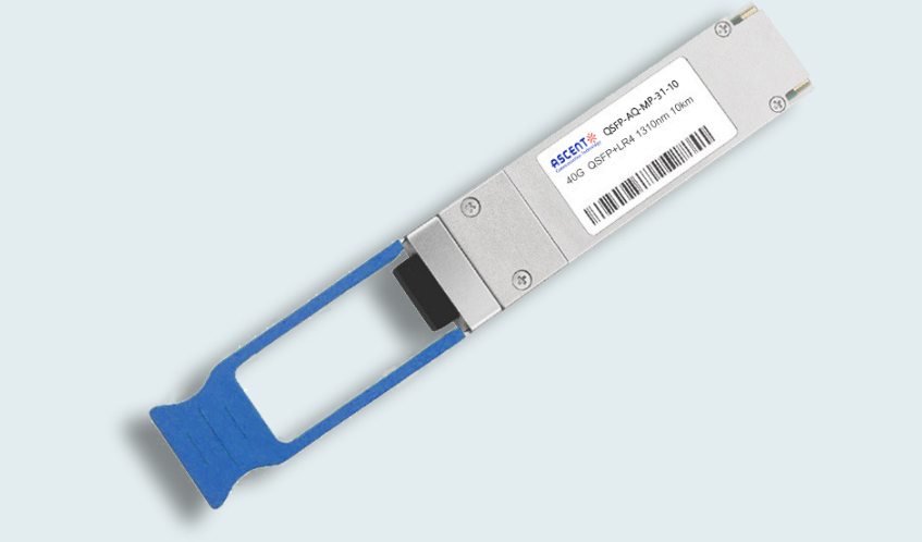
40G QSFP+ PLR4 1310 nm 10 km
QSFP-AQ-MP-31-10 40 Gb/s QSFP+ PSM 1310nm 10km MPO Optical Transceiver

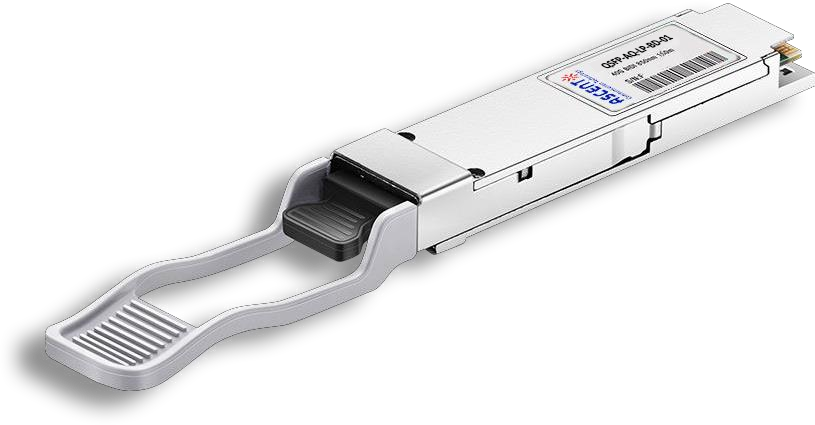
40G QSFP+ CSR4 300m
40 Gb/s 300m QSFP+ CSR4 Transceiver
40GBASE-UNIV QSFP+ MMF and SMF
40G QSFP+ UNIV MMF/SMF 150m/2km
40G QSFP+ CWDM 2 km
40G QSFP+ CWDM 2 km
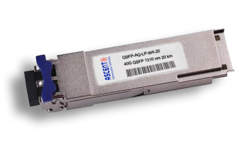
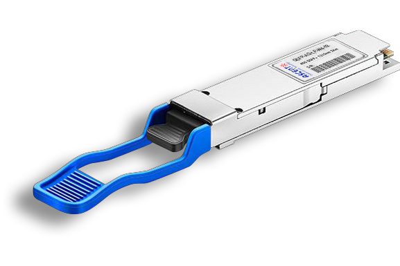
40G QSFP CWDM 20 km
QSFP-AQ-LP-W4-20 40 Gb/s QSFP CWDM 20 km Transceiver
40G QSFP+ BIDI 150m
40 Gb/s QSFP+ BiDi Transceiver 150m
32G SFP28 1310 nm 10 km
32G FC 1310 nm 10 km SFP28 Transceiver

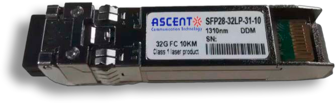
32G SFP28 SR 850 nm 100 m
SFP28-32LP-85-01 32GBASE-SR SFP28 850 nm 100 m DOM Transceiver
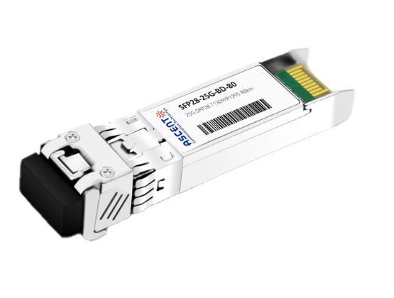
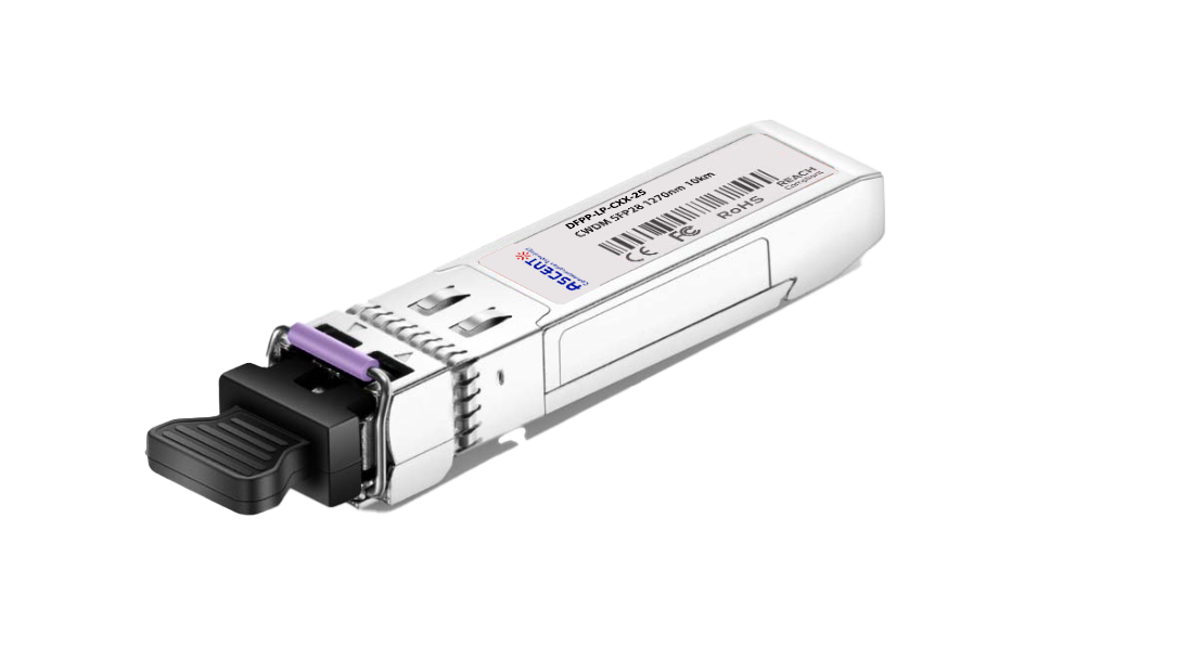
25G SFP28 BIDI 80 km
25G SFP28 BIDI 80 km Transceiver
.png)
25G SFP28 CWDM 10 km(E)
25 Gb/s CWDM EML SFP28 10 km Transceiver
25G SFP28 CWDM 10 km(D)
25 Gb/s CWDM SFP28 10 km Transceiver
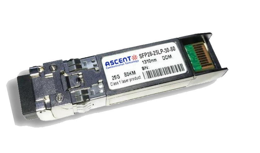
25G SFP28 ZR 1310nm 80km
25 Gbps 1310 nm 80 km SFP28 ZR Transceiver
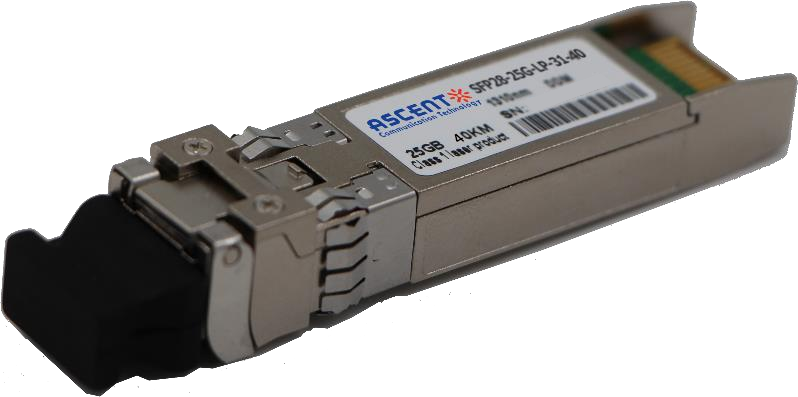
25G SFP28 1310 nm 40km
25 Gb/s 1310 nm Single-Mode SFP28 Transceiver
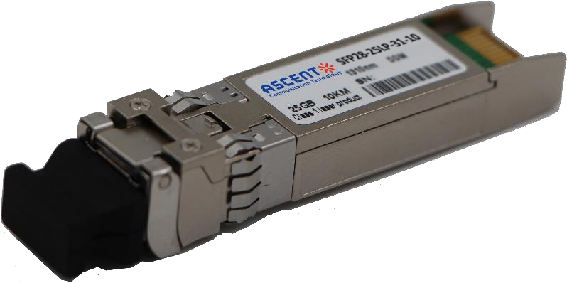
25G SFP28 1310 nm 10 km
SFP28-25LP-31-10 25 Gb/s 1310 nm Single-Mode SFP+ Transceiver
25G SFP28 850 nm 300m
25 Gb/s 850 nm Multi-Mode SFP28 300m Transceiver
25G SFP28 850 nm 100m
SFP28-25LP-85-01 28 Gb/s 850 nm Multi-Mode SFP28 Transceiver

10/25G SFP28 1310nm 40km
10/25 Gb/s SFP28 1310 nm 40km Transceiver
10/25G SFP28 1310nm 10km
10/25 Gb/s SFP28 1310 nm 10km DDM Transceiver

10/25G SFP28 850 nm 300m
10/25 Gb/s SFP28 850 nm 300m Transceiver

10/25G SFP28 850 nm 100m
10/25 Gb/s SFP28 850 nm 100m Transceiver
White Paper
Press Releases
Briefings 1
Briefings 2
Videos, etc.
QRG
Manual1
Manual2
Get in touch with our experts
Feedback