- FIBER OPTIC TRANSCEIVERS >10G Transceivers >16G SFP+ FC 850 nm 100 m
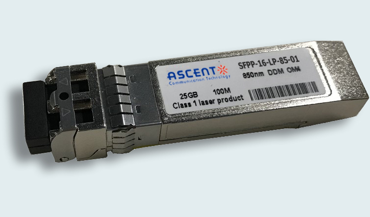
16G SFP+ FC 850 nm 100 m
Ascentãs SFPP-16-LP-85-01 SFP+ transceiver is an integrated ÿ˜ber optic transceiver that provides a high-speed serial link at signaling rates up to 16 Gb/s.
ã Up to 14.025 Gbps Data Link
ã Maximum link length of 100 m links on OM3 or
ã 150 m links on OM4 multi-mode fiber
ã Power dissipation < 1W
ã VSCEL laser and PIN receiver
ã Metal enclosure, for lower EMI
ã 2-wire interface with integrated Digital Diagnostic monitoring
ã Hot-pluggable SFP+ footprint
ã Specifications compliant with SFF 8472
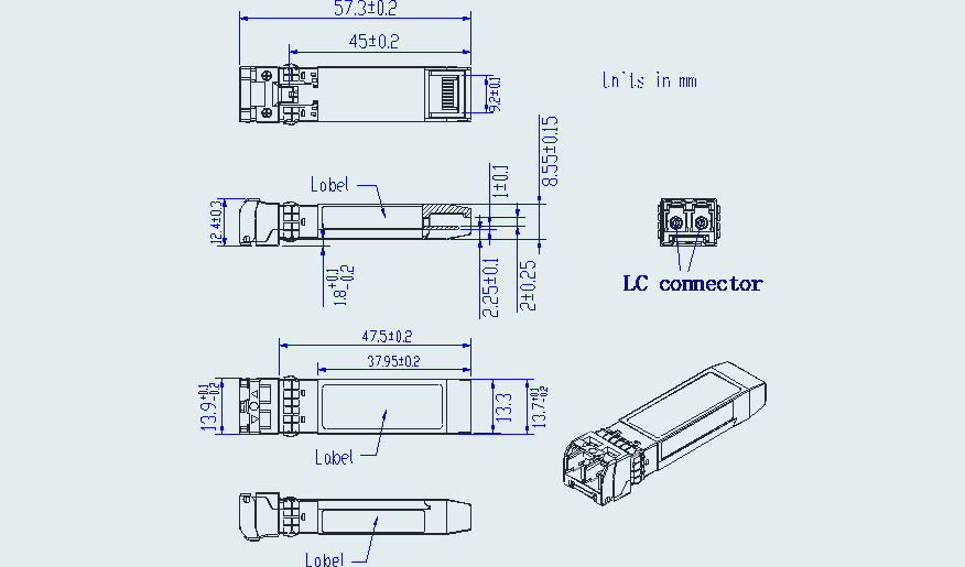
ã Compliant with SFP+ MSA with LC connector
ã Single 3.3V power supply
ã Case operating temperature range: Commercial: 0 ô¯C to +70 ô¯C
Absolute Maximum Ratings
Parameter | Symbol | Min. | Typ. | Max. | Unit | Notes |
Storage Temperature | Ts | ã40 | ã | 85 | ô¯C | |
Relative Humidity | RH | 5 | ã | 95 | % | |
Power Supply Voltage | VCC | ã0.3 | ã | 4 | V | |
Signal Input Voltage | Vccã0.3 | ã | Vcc+0.3 | V |
Recommended Operating Conditions
Parameter | Symbol | Min. | Typ. | Max. | Unit | Note |
Case Operating Temperature | Tcase | 0 | ã | 70 | ô¯C | Commercial |
Power Supply Voltage | VCC | 3.14 | 3.3 | 3.47 | V | |
Power Supply Current | ICC | ã | 300 | mA | ||
Data Rate | BR | 14.025 | Gbps | |||
Transmission Distance | TD | ã | 150 | m | OM4 or 100m OM3 | |
Coupled Fiber | Multiãmode fiber | 50/125um OM4 | ||||
Optical Characteristics
Parameter | Symbol | Min. | Typ. | Max. | Unit | Notes |
Transmitter | ||||||
Output Opt. Power | POUT | ã7.8 | 2.4 | dBm | 1 | |
Optical Wavelength | ö£ | 840 | 850 | 860 | nm | |
Spectral Width (RMS) | ü | 0.6 | nm | |||
Optical Extinction Ratio | ER | 3.0 | dB | |||
RIN | RIN | ã128 | dB/Hz | |||
Receiver | ||||||
Rx Sensitivity | RSENS | ã10.5 | dBm | 2 | ||
Input Saturation Power (Overload) | Psat | 0 | dBm | |||
Wavelength Range | ö£C | 770 | 850 | 860 | nm | |
LOS De ãAssert | LOSD | ã13 | dBm | |||
LOS Assert | LOSA | ã30 | dBm | |||
LOS Hysteresis | 0.5 | dB |
Notes:
1. Class 1 Laser Safety per FDA/CDRH and IECã825ã1 regulations.
2. Measured with a PRBS 231ã1 test pattern, @14.025 Gb/s, BER<10ã12
Electrical Characteristics
Parameter | Symbol | Min. | Typ. | Max. | Unit | Notes |
Supply Voltage | Vcc | 3.14 | 3.3 | 3.46 | V | |
Supply Current | Icc | 300 | mA | |||
Transmitter | ||||||
Input Differential Impedance | Rin | 100 | öˋ | 1 | ||
Single Ended Data Input Swing | Vin, pp | 180 | 700 | mV | ||
Transmit Disable Voltage | VD | Vccã1.3 | Vcc | V | ||
Transmit Enable Voltage | VEN | Vee | Vee+ 0.8 | V | 2 | |
Receiver | ||||||
Differential Data Output Swing | Vout, pp | 300 | 850 | mV | 3 | |
LOS Fault | VLOS fault | Vccã1.3 | VccHOST | V | 4 | |
LOS Normal | VLOS norm | Vee | Vee+0.8 | V | 4 |
Notes:
1. Connected directly to TX data input pins. AC coupled thereafter.
2. Or open circuit.
3. Into 100 öˋ differential termination.
4. Loss Of Signal is LVTTL. Logic 0 indicates normal operation; logic 1 indicates no signal detected.

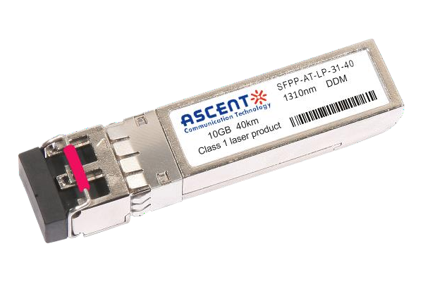
10G SFP+ LR 1310 nm 40 km
10 Gb/s 1310nm SFP+ 40 km Transceiver

10G SFP+ LR 1310 nm 20 km
SFPP-ATLP-31-20 SFP+ Plug-in, 10Gbps, 20km, TX=1310/RX wide, on two single mode fibers, LC/PC Blue
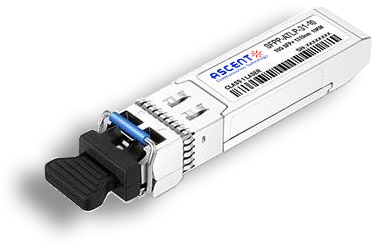
10G SFP+ LR 1310 nm 10 km
SFPP-ATLP-31-10 SFP+ Plug-in, 10Gbps, 10km, TX=1310/RX wide, on two single mode fibers, LC/PC Blue

10G SFP+ LRM 1310 nm 2 km
SFPP-ATLP-31-02 10Gb/s 1310nm SFP+ 2 km Transceiver
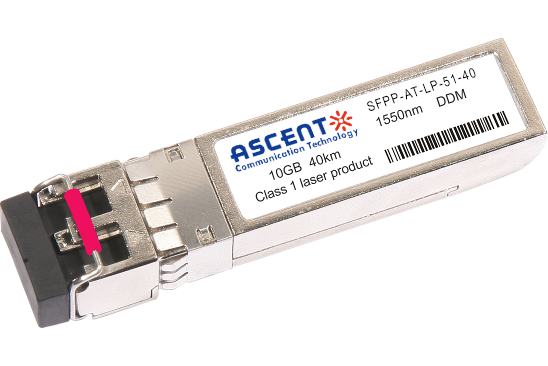
10G SFP+ ER 1550 nm 40 km
SFPP-ATLP-51-40 10 Gb/s 1550 nm SFP+ 40 km Transceiver
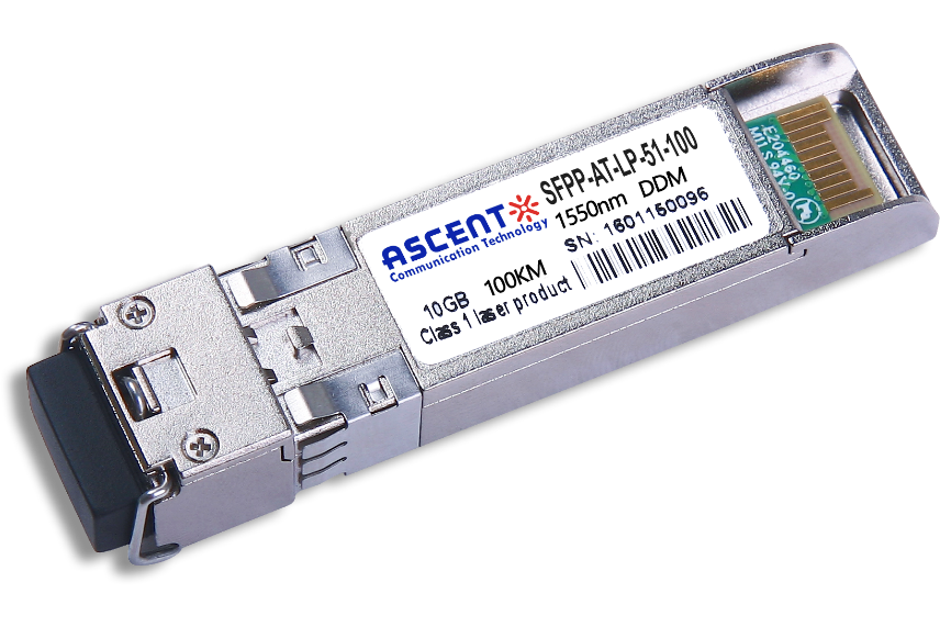
10G SFP+ CDR 1550 nm 100 km
SFPP-ATLP-51-100 10 Gb/s 1550 nm SFP+ 100 km Transceiver
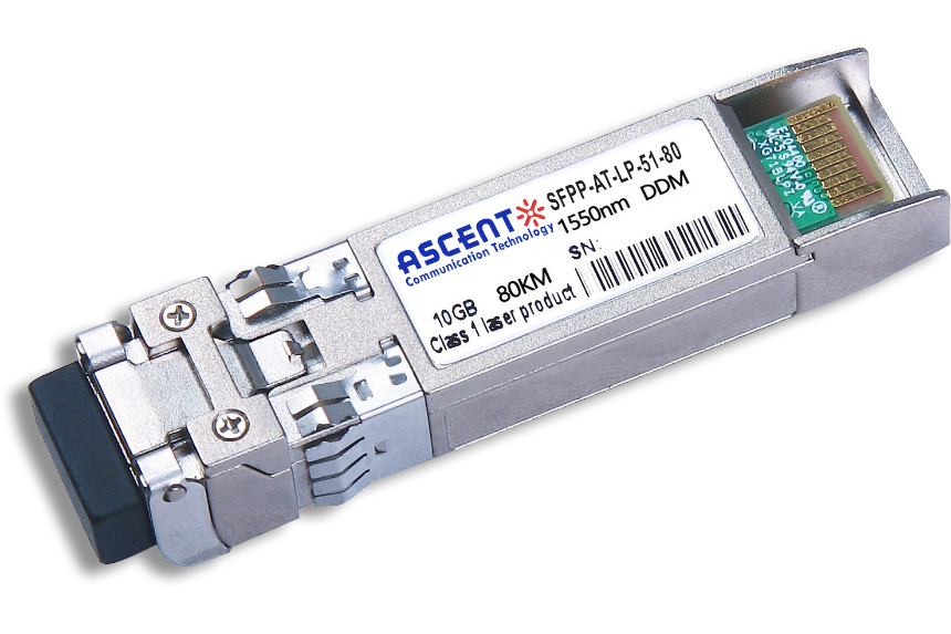
10G SFP+ ZR 1550 nm 80 km
SFPP-ATLP-51-80 10 Gb/s 1550 nm SFP+ 80 km Transceiver
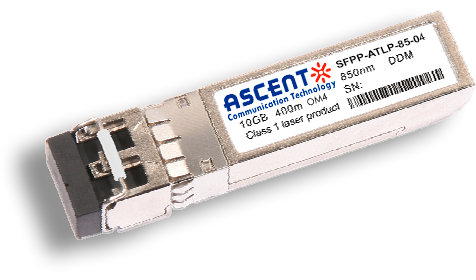
10G SFP+ 850 nm 400 m
10 Gb/s 850nm Multi-mode SFP+ Transceiver 400m
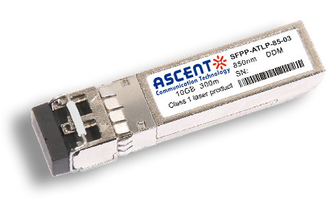
10G SFP+ 850 nm 300 m
SFPP-ATLP-85-03 10 Gb/s 850nm Multi-Mode SFP+ Transceiver
10G SFP+ Tunable DWDM 80 km
SFPP-LP-T99R-80 10 Gb/s Tunable DWDM SFP+ 80 km Transceiver
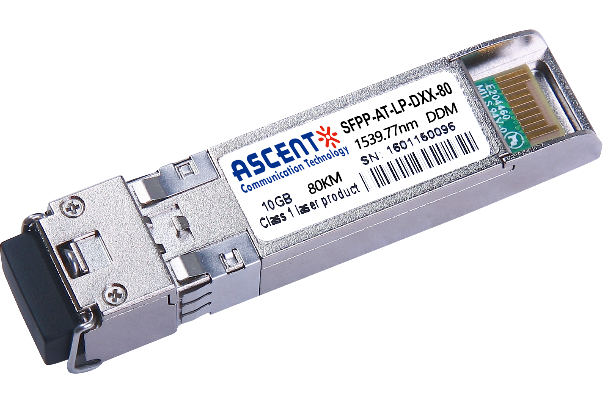
10G SFP+ DWDM 80 km
SFPP-ATLP-DXX-80 10 Gb/s DWDM SFP+ 80 km Transceiver
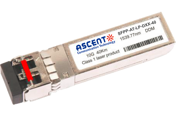
10G SFP+ DWDM 40 km
SFPP-ATLP-DXX-40 SFP+ Plug-in, 10Gbps, 40km, TX=ITU Ch xx (17 to 61) /RX wide, on two single mode fibers, LC/PC Blue
10G SFP+ CWDM 80 km
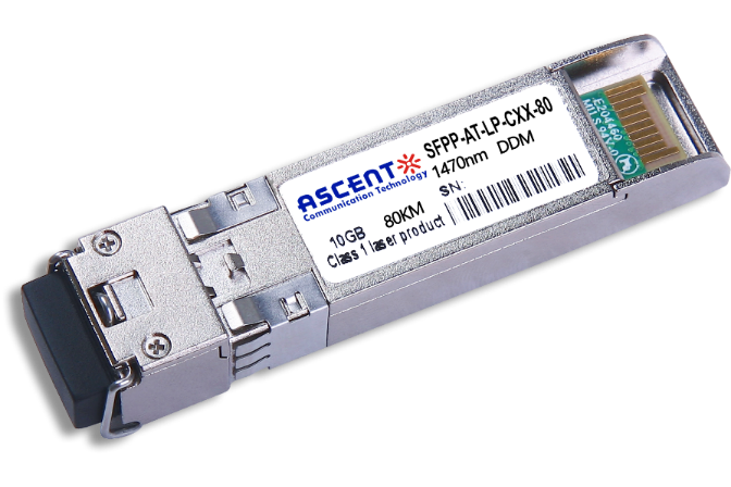
SFPP-ATLP-CXX-80 SFP+ Plug-in, 10 Gbps, 80 km, TX = CWDM Ch xx (1470ô nm to 1610 nm)/RX wide, on two single-mode fibers, LC/PC Blue.
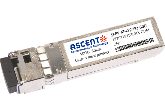
10G SFP+ CWDM 2733 60 km
SFPP-AT-LP-XXXX-60D 10 Gb/s BIDI SFP+ 60 km Transceiver
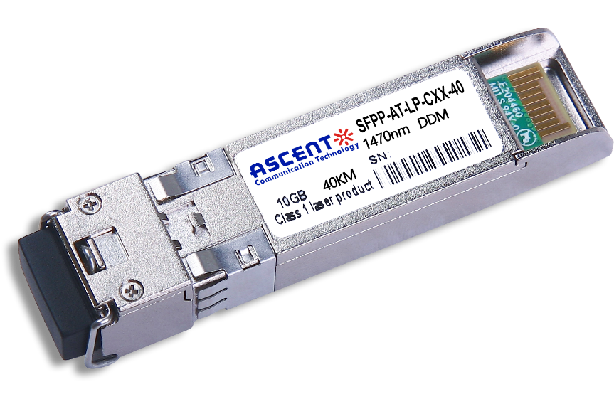
10G SFP+ CWDM 40 km
SFPP-ATLP-CXX-40 SFP+ Plug-in, 10Gbps, 40km, TX=CWDM Ch xx (1270ô nm to 1610 nm) /RX wide, on two single mode fibers, LC/PC Blue
10G SFP+ CWDM 10 km
10 Gb/s CWDM SFP+ 10 km Transceiver
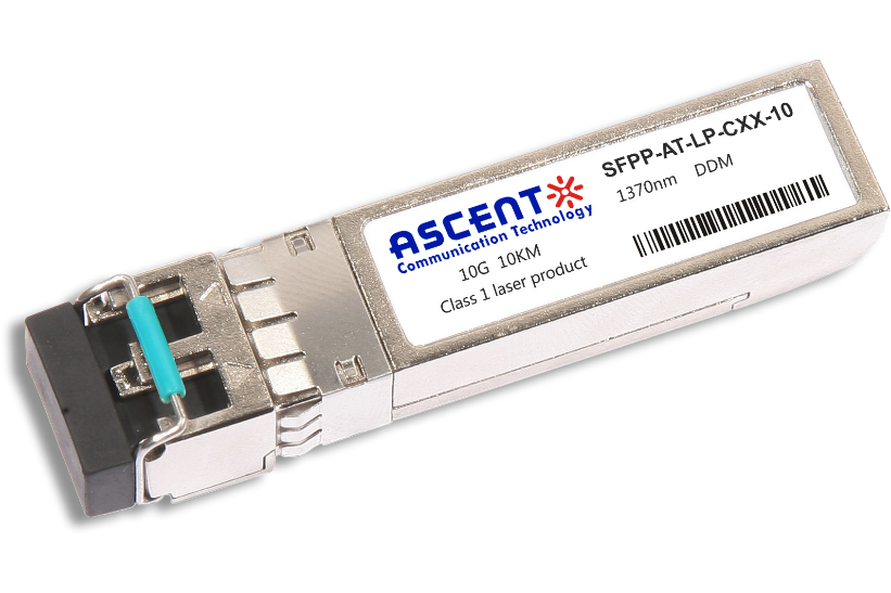
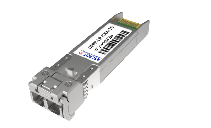
10G SFP+ Single mode CWDM 10 km
SFPP-ATLP-CXX-10 SFP+ Plug-in, 10 Gbps, 10 km, TX=CWDM Ch xx (1270 nm to 1610 nm)/RX wide, on two single-mode fibers, LC/PC Blue
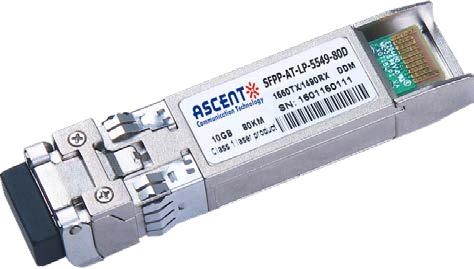
10G SFP+ CWDM 4955 80 km
SFP+ BIDI 10 Gb/s 1490/1550 nm 80 km Transceiver
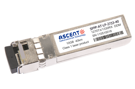
10G SFP+ CWDM 2733 40 km
SFPP-AT-LP-XXXX-40 SFP+ Plug-in, 10Gbps, 40km, TX=1270/RX=1330 , on one single mode fibers, LC/PC Blue
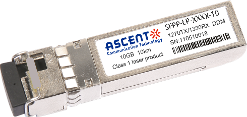
10G SFP+ CWDM 2733 10 km
SFPP-LP-XXXX-10 SFP+ Plug-in, 10Gbps, 10km, TX=1270/RX=1330 , on one single mode fibers, LC/PC Blue

10G XFP BIDI 80KM
XFP 10 Gb/s BIDI Single-Mode 80 km Transceiver DDM

10G XFP BIDI 40KM
XFP 10 Gb/s BIDI Single-Mode 40 km Transceiver DDM

10G XFP BIDI 20KM
XFP 10 Gb/s BIDI Single-Mode 20 km Transceiver DDM

10G XFP BIDI 10KM
XFP 10 Gb/s BIDI Single-Mode 10 km Transceiver DDM

10G XFP LR 1310 nm 20 km
XFP-AT-LP-31-20 10 Gb/s 20 km XFP Transceiver

10G XFP LR 1310 nm 10 km
XFP-AT-LP-31-10 10 Gb/s 10 km XFP Transceiver
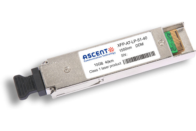
10G XFP ER 1550 nm 40 km
XFP-AT-LP-51-40 10 Gb/s 40 km XFP Optical Transceiver

10G XFP ZR 1550 nm 80 km
XFP-AT-LP-51-80 10 Gb/s 80 km XFP Optical Transceiver
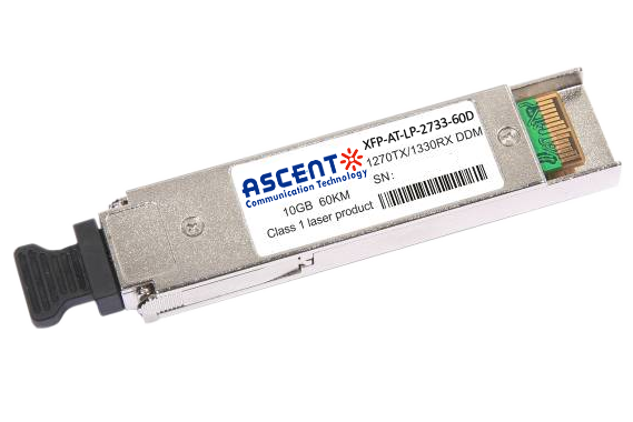
10G XFP CWDM 2633 60 km
XFP-ATLP-XXXX-60 10 Gb/s BIDI XFP 60 km Transceiver
10G SFP+ CWDM 1610 80 km
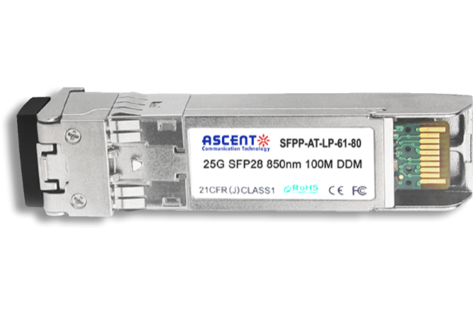
SFPP-ATLP-61-80 SFP+ Plug-in, 10Gbps, 80km, TX=1610/RX wide, on two single mode fibers, LC/PC Blue
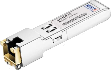
10G SFP+ Copper RJ45 30 m
SFPP-AT-CO-03 10GBASE-T SFP+ Copper RJ45 30m Transceiver

10G X2 850nm 300m
X2 10Gb/s 850nm Multi-mode Transceiver 300m
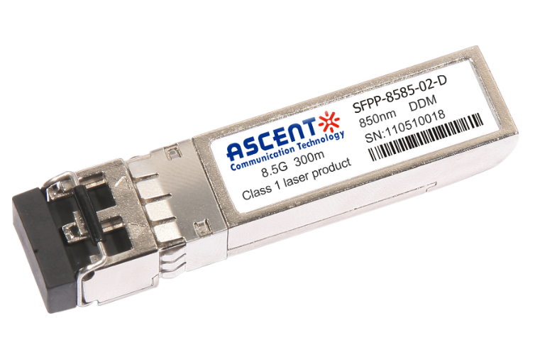
8.5G SFP+ SR 850 nm 150 m
SFPP-A8LP-85-015 8.5 Gb/s 850 nm Multi-Mode SFP+ Transceiver
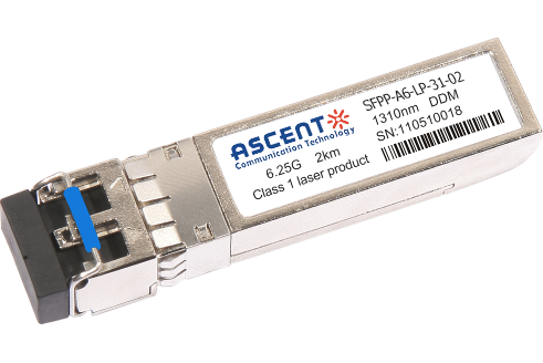
6.25G SFP+ LRM 1330 nm 2 km
SFPP-A6-LP-31-02 6.25 Gb/s Single-Mode SFP+ Transceiver
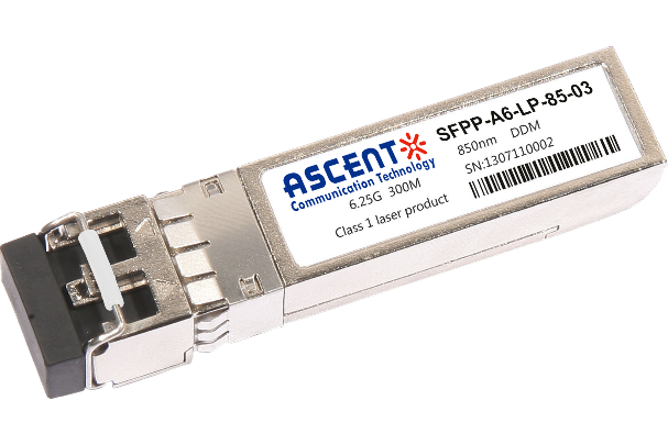
6.25G SFP+ SR 850 nm 300 m
SFPP-A6-LP-85-03 6.25 Gb/s 850 nm Multi-Mode SFP+ Transceiver
White Paper
Press Releases
Briefings 1
Briefings 2
Videos, etc.
QRG
Manual1
Manual2
Get in touch with our experts
Feedback