- FIBER OPTIC TRANSCEIVERS >10G Transceivers >10G SFP+ Single mode CWDM 10 km

10G SFP+ Single mode CWDM 10 km
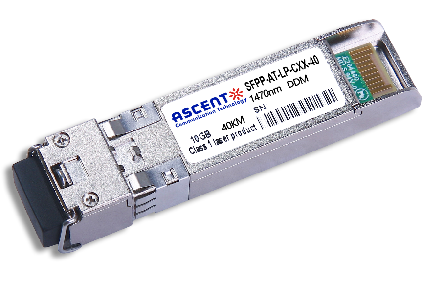
ASCENTãs CWDM SFP+ transceivers are designed for use in 10-Gigabit Ethernet links with distances up to 10 km over single-mode fiber. These transceivers include a PIN photo detector diode and uncooled CWDM DFB laser transmitter. Digital diagnostic functions are available via an I2C interface. This module is designed for single-mode fiber and operates at wavelengths between 1270 nm to 1610 nm.
ãÂô ô ô Up to 11.3 Gbps Data Links
ãÂô ô ô Up to 10 km transmission on SMF
ãÂô ô ô Power dissipation < 1.5W
ãÂô ô ô Uncooled CWDM DFB Laser and PIN receiver
ãÂô ô ô Metal enclosure, for lower EMI
ãÂô ô ô 2-wire interface with integrated Digital Diagnostic monitoring
ãÂô ô ô Hot-pluggable SFP+ footprint
ãÂô ô ô Specifications compliant with SFF 8472
ãÂô ô ô Compliant with SFP+ MSA with LC connector
ãÂô ô ô Single 3.3V power supply
ãÂô ô ô Case operating temperature range: 0ô¯C to +70 ô¯C
ãÂô ô ô Compliant to 802.3ae 10GBASE-LR/LW
Parameter | Symbol | Min. | Typ. | Max. | Unit | Note |
Storageô Temperature | Ts | ã40 | ã | 85 | ô¯C | |
Relativeô Humidity | RH | 5 | ã | 95 | % | |
Powerô Supplyô Voltage | VCC | ã0.3 | ã | 4 | V | |
Signalô Inputô Voltage | Vccã0.3 | ã | Vcc+0.3 | V |
ô
Recommendedô Operatingô Conditions
Parameter | Symbol | Min. | Typ. | Max. | Unit | Note |
Caseô Operatingô Temperature | Tcase | 0 | ã | 70 | ô¯C | Withoutô airô flow |
Powerô Supplyô Voltage | VCC | 3.14 | 3.3 | 3.47 | V | |
Powerô Supplyô Current | ICC | ã | 450 | mA | ||
Dataô Rate | BR | 10.3125 | 11.3 | Gbps | ||
Transmissionô Distance | TD | ã | 10 | km | ||
Coupledô fiber | Singleô modeô fiber | 9/125ô ôçmô SMF | ||||
ô
Opticalô Characteristicsô
Parameter | Symbol | Min. | Typ. | Max. | Unit | Note |
Transmitter | ||||||
Outputô Opt.ô Power | POUT | ã6 | ã0.5 | dBm | 1 | |
Opticalô Wavelength | ö£ | ö£ã6.5 | ö£+6.5 | nm | 2 | |
Spectralô Widthô (ã20dB) | ü | 1 | nm | |||
Opticalô Extinctionô Ratio | ER | 3.5 | dB | |||
Sideô modeô Suppressionô ratio | SMSR | 30 | dB | |||
Outputô Eyeô Mask | Compliantô withô IEEEô 802.3ae | |||||
Receiver | ||||||
Receiverô Sensitivityô | Psen | ã14.4 | dBm | 3 | ||
Inputô Saturationô Powerô (Overload) | PSAT | 0.5 | dBm | |||
Inputô Opticalô Wavelength | ö£IN | 1270 | 1610 | nm | ||
LOSô Assertô | LOSA | ã30 | dBm | |||
LOSô Deãassertô | LOSD | ã17 | dBm | |||
LOSô ãHysteresis | PHys | 0.5 | dB | |||
Notes:ô ô
1.ô Classô 1ô Laserô Safetyô perô FDA/CDRHô andô IECã825ã1ô regulations.
2.ô ö£ô is:ô 1270,ô 1290,ô 1310,ô 1330,ô 1350,ô 1370,ô 1390,ô 1410,ô 1430,ô 1450,ô 1470,ô 1490,ô 1510,ô 1530,ô 1550,ô 1570,ô 1590,ô 1610.
3.ô Measuredô withô aô PRBSô 231ã1ô testô pattern,ô @ô 10.325Gb/s,ô BER<10ã12.ô
ô
Electricalô Characteristicsô
Parameter | Symbol | Min | Typ. | Max | Unit | Note |
Supplyô Voltage | Vcc | 3.14 | 3.3 | 3.46 | V | |
Supplyô Current | Icc | 450 | mA | |||
Transmitter | ||||||
Inputô differentialô impedance | Rin | 100 | öˋ | 1 | ||
Differentialô dataô inputô swing | Vin,ô pp | 180 | 1200 | mV | ||
Transmitô Disableô Voltage | VD | Vccã1.3 | Vcc | V | ||
Transmitô Enableô Voltage | VEN | Vee | Vee+ô 0.8 | V | 2 | |
Transmitô Disableô Assertô Time | 10 | us | ||||
Receiver | ||||||
Differentialô dataô outputô swing | Vout,ô pp | 300 | 850 | mV | 3 | |
Dataô outputô riseô time | tr | 30 | ps | 4 | ||
Dataô outputô fallô time | tf | 30 | ps | 4 | ||
LOSô Fault | VLOSô fault | Vccã1.3 | VccHOST | V | 5 | |
LOSô Normal | VLOSô norm | Vee | Vee+0.8 | V | 5 |
Notes:ô
1.ô Connectedô directlyô toô TXô dataô inputô pins.ô ACô coupledô thereafter.ô ô
2.ô Orô openô circuit.ô ô
3.ô Inputô 100ô öˋô differentialô termination.ô ô
4.ô Theseô areô unfilteredô 20ô %ô toô 80ô %ô values
5.ô Lossô Ofô Signalô isô LVTTL.ô Logicô 0ô indicatesô normalô operation;ô logicô 1ô indicatesô noô signalô detected.ô ô

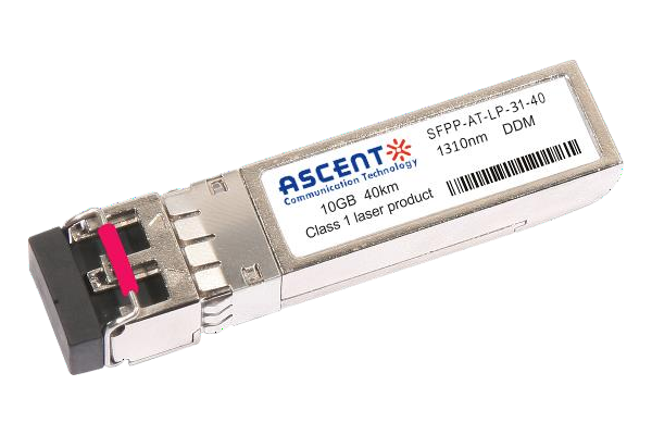
10G SFP+ LR 1310 nm 40 km
10 Gb/s 1310nm SFP+ 40 km Transceiver

10G SFP+ LR 1310 nm 20 km
SFPP-ATLP-31-20 SFP+ Plug-in, 10Gbps, 20km, TX=1310/RX wide, on two single mode fibers, LC/PC Blue
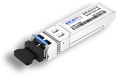
10G SFP+ LR 1310 nm 10 km
SFPP-ATLP-31-10 SFP+ Plug-in, 10Gbps, 10km, TX=1310/RX wide, on two single mode fibers, LC/PC Blue

10G SFP+ LRM 1310 nm 2 km
SFPP-ATLP-31-02 10Gb/s 1310nm SFP+ 2 km Transceiver
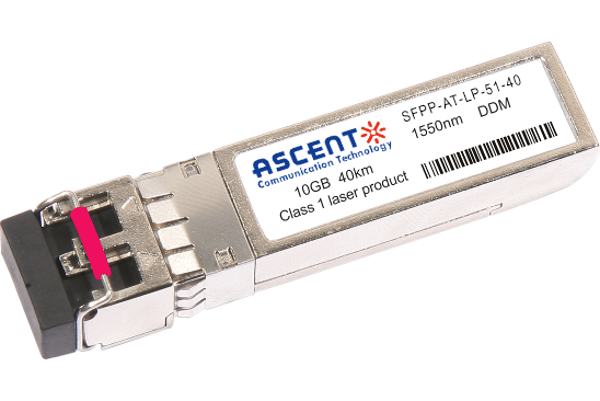
10G SFP+ ER 1550 nm 40 km
SFPP-ATLP-51-40 10 Gb/s 1550 nm SFP+ 40 km Transceiver
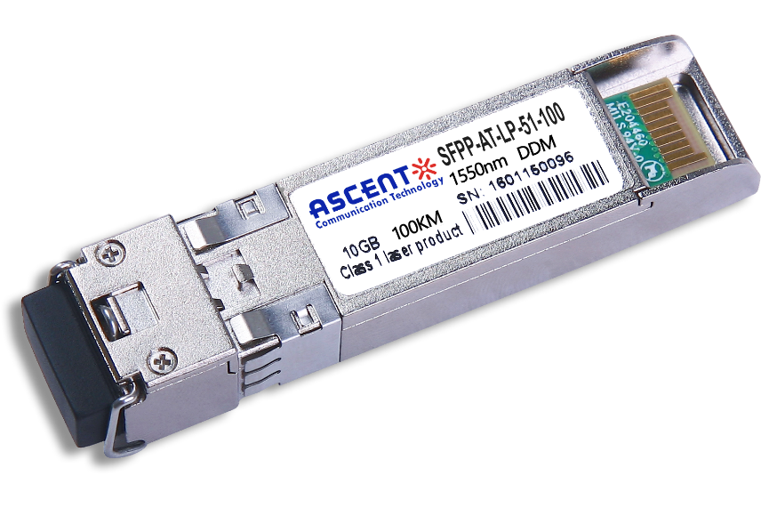
10G SFP+ CDR 1550 nm 100 km
SFPP-ATLP-51-100 10 Gb/s 1550 nm SFP+ 100 km Transceiver
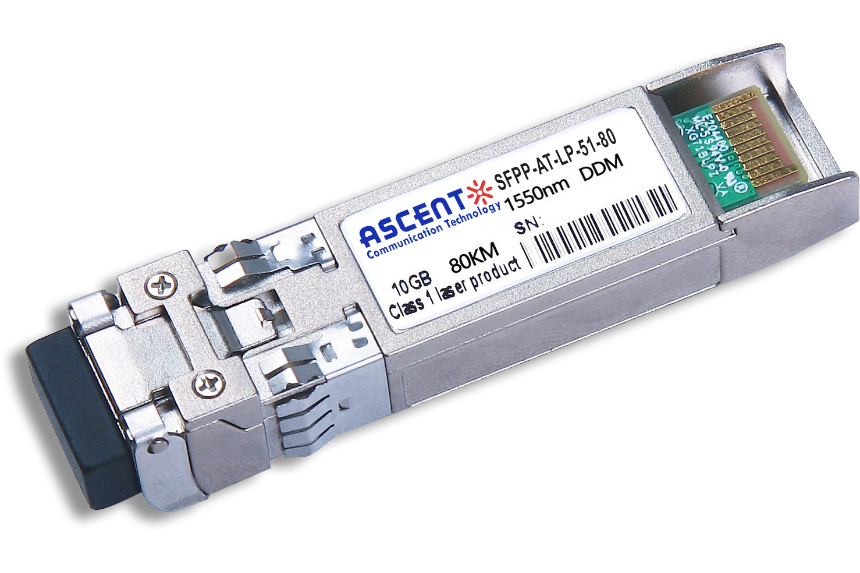
10G SFP+ ZR 1550 nm 80 km
SFPP-ATLP-51-80 10 Gb/s 1550 nm SFP+ 80 km Transceiver
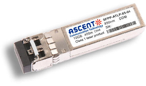
10G SFP+ 850 nm 400 m
10 Gb/s 850nm Multi-mode SFP+ Transceiver 400m
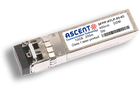
10G SFP+ 850 nm 300 m
SFPP-ATLP-85-03 10 Gb/s 850nm Multi-Mode SFP+ Transceiver
10G SFP+ Tunable DWDM 80 km
SFPP-LP-T99R-80 10 Gb/s Tunable DWDM SFP+ 80 km Transceiver
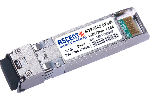
10G SFP+ DWDM 80 km
SFPP-ATLP-DXX-80 10 Gb/s DWDM SFP+ 80 km Transceiver
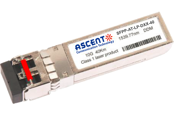
10G SFP+ DWDM 40 km
SFPP-ATLP-DXX-40 SFP+ Plug-in, 10Gbps, 40km, TX=ITU Ch xx (17 to 61) /RX wide, on two single mode fibers, LC/PC Blue
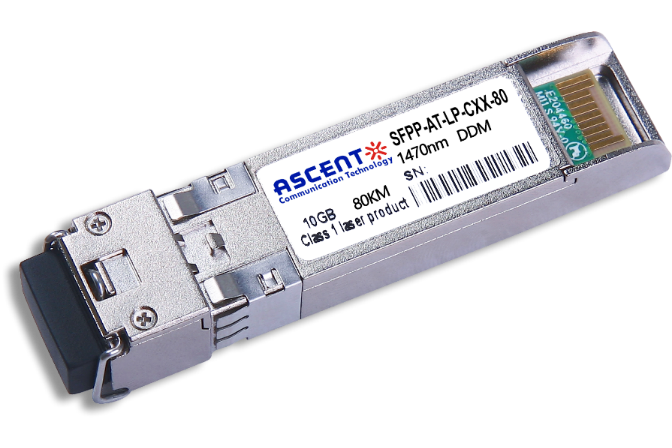
10G SFP+ CWDM 80 km
SFPP-ATLP-CXX-80 SFP+ Plug-in, 10 Gbps, 80 km, TX = CWDM Ch xx (1470ô nm to 1610 nm)/RX wide, on two single-mode fibers, LC/PC Blue.
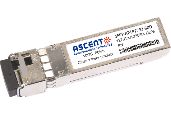
10G SFP+ CWDM 2733 60 km
SFPP-AT-LP-XXXX-60D 10 Gb/s BIDI SFP+ 60 km Transceiver
10G SFP+ CWDM 40 km
SFPP-ATLP-CXX-40 SFP+ Plug-in, 10Gbps, 40km, TX=CWDM Ch xx (1270ô nm to 1610 nm) /RX wide, on two single mode fibers, LC/PC Blue
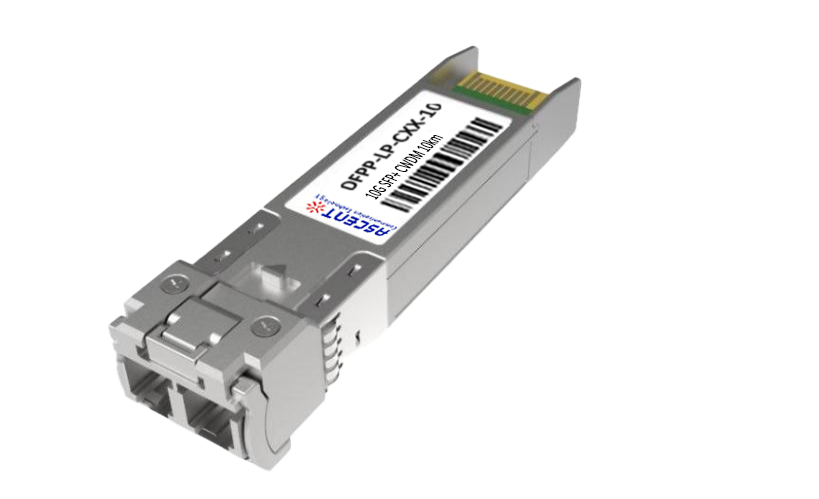
10G SFP+ CWDM 10 km
10 Gb/s CWDM SFP+ 10 km Transceiver
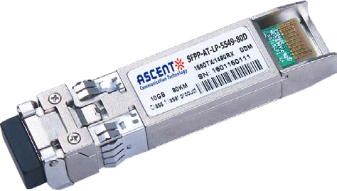
10G SFP+ CWDM 4955 80 km
SFP+ BIDI 10 Gb/s 1490/1550 nm 80 km Transceiver
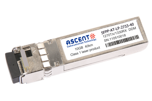
10G SFP+ CWDM 2733 40 km
SFPP-AT-LP-XXXX-40 SFP+ Plug-in, 10Gbps, 40km, TX=1270/RX=1330 , on one single mode fibers, LC/PC Blue
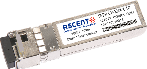
10G SFP+ CWDM 2733 10 km
SFPP-LP-XXXX-10 SFP+ Plug-in, 10Gbps, 10km, TX=1270/RX=1330 , on one single mode fibers, LC/PC Blue

10G XFP BIDI 80KM
XFP 10 Gb/s BIDI Single-Mode 80 km Transceiver DDM

10G XFP BIDI 40KM
XFP 10 Gb/s BIDI Single-Mode 40 km Transceiver DDM

10G XFP BIDI 20KM
XFP 10 Gb/s BIDI Single-Mode 20 km Transceiver DDM

10G XFP BIDI 10KM
XFP 10 Gb/s BIDI Single-Mode 10 km Transceiver DDM

10G XFP LR 1310 nm 20 km
XFP-AT-LP-31-20 10 Gb/s 20 km XFP Transceiver

10G XFP LR 1310 nm 10 km
XFP-AT-LP-31-10 10 Gb/s 10 km XFP Transceiver
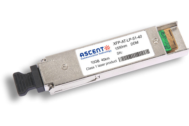
10G XFP ER 1550 nm 40 km
XFP-AT-LP-51-40 10 Gb/s 40 km XFP Optical Transceiver

10G XFP ZR 1550 nm 80 km
XFP-AT-LP-51-80 10 Gb/s 80 km XFP Optical Transceiver
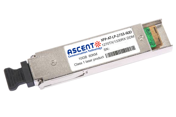
10G XFP CWDM 2633 60 km
XFP-ATLP-XXXX-60 10 Gb/s BIDI XFP 60 km Transceiver
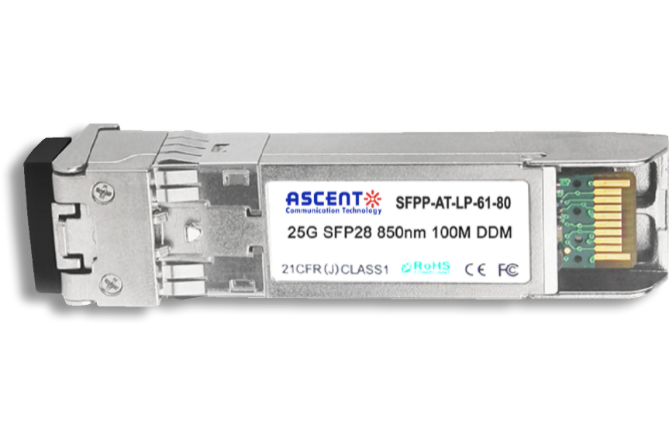
10G SFP+ CWDM 1610 80 km
SFPP-ATLP-61-80 SFP+ Plug-in, 10Gbps, 80km, TX=1610/RX wide, on two single mode fibers, LC/PC Blue
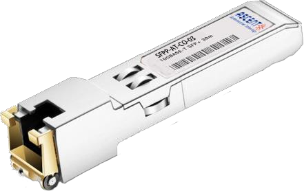
10G SFP+ Copper RJ45 30 m
SFPP-AT-CO-03 10GBASE-T SFP+ Copper RJ45 30m Transceiver

10G X2 850nm 300m
X2 10Gb/s 850nm Multi-mode Transceiver 300m
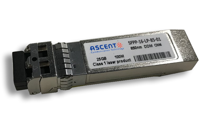
16G SFP+ FC 850 nm 100 m
SFPP-16-LP-85-01 16 Gb/s 850 nm SFP+ 100 m Transceiver
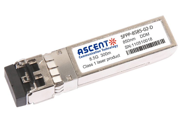
8.5G SFP+ SR 850 nm 150 m
SFPP-A8LP-85-015 8.5 Gb/s 850 nm Multi-Mode SFP+ Transceiver
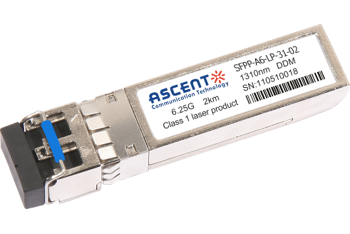
6.25G SFP+ LRM 1330 nm 2 km
SFPP-A6-LP-31-02 6.25 Gb/s Single-Mode SFP+ Transceiver
6.25G SFP+ SR 850 nm 300 m
SFPP-A6-LP-85-03 6.25 Gb/s 850 nm Multi-Mode SFP+ Transceiver
White Paper
Press Releases
Briefings 1
Briefings 2
Videos, etc.
QRG
Manual1
Manual2
Get in touch with our experts
Feedback