- FTTH ã 10G XGSPON >SFP Transceivers >1.25G SFP CWDM 4931 20 km
1.25G SFP CWDM 4931 20 km
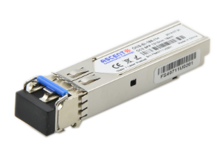
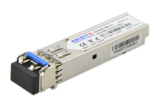
ACTãs SFP-AG-SP-4931 transceiver is a flexible solution as an interface for switches, routers, servers, and other optical links. This SFP transceiver can carry data links at rates up to 1.25 Gb/s, and is compatible with the SFP Multi-Sourcing Agreement (MSA). The transceiver module covers data link up to 20KM in 9/125um single mode fiber. It is BIDI with the 1310nm FP laser and the 1550nm DFB laser.
ã Up to 1.25 Gb/s data links
ã DFB laser transmitter
ã PIN photodetector
ã Up to 20 km on 9/125ôçm SMF
ã Hot-pluggable SFP footprint
ã BIDI LC/UPC type pluggable optical interface
ã Low power dissipation
ã Metal enclosure for lower EMI
ã RoHS compliant and lead-free
ã Supports the Digital Diagnostic Monitoring interface
ã Compliant with SFF-8472
Absolute Maximum Ratings
Parameter | Symbol | Min. | Typ. | Max. | Unit | Note |
Storage Temperature | Ts | ã40 | 85 | ô¯C | ||
Relative Humidity | RH | 5 | 95 | % | ||
Power Supply Voltage | VCC | ã0.5 | 4 | V | ||
Signal Input Voltage | ã0.3 | Vcc+0.3 | V | |||
Receiver Damage Threshold | 5 | dBm |
Recommended Operating Conditions
Parameter | Symbol | Min. | Typ. | Max. | Unit | Note |
Case Operating Temperature | Tcase | 0 | 70 | ô¯C | SFPãAGãSPã4931 | |
ã10 | 80 | SFPãAGãSPã4931E | ||||
ã40 | 85 | SFPãAGãSPã4931A | ||||
Power Supply Voltage | VCC | 3.13 | 3.3 | 3.47 | V | |
Power Supply Current | ICC | 280 | mA | |||
Power Supply Noise Rejection | 100 | mVpãp | 100 Hz to 1 MHz | |||
Data Rate | 1.25/1.25 | Gbps | TX Rate/RX Rate | |||
Transmission Distance | 20 | kM | ||||
Coupled Fiber | Singleãmode fiber | 9/125 ôçm SMF | ||||
Transmitter Specifications
Parameter | Symbol | Min. | Typ. | Max. | Unit | Note |
Average Output Power | POUT | ã9 | ã3 | dBm | 1 | |
Extinction Ratio | ER | 9 | dB | |||
Center Wavelength | ö£C | 1290 | 1310 | 1330 | nm | SFPãAGãSPã4931 |
1470 | 1490 | 1510 | SFPãAGãSPã3149 | |||
Side Mode Suppression Ratio | SMSR | 30 | dB | DFB Laser
| ||
Spectrum Bandwidth(ã20dB) | ü | 1 | nm | |||
Transmitter OFF Output Power | POff | ã45 | dBm | |||
Differential Line Input Impedance | RIN | 90 | 100 | 110 | öˋ | |
Output Eye Mask | Compliant with IEEE802.3 z (class 1 laser safety) | 2 | ||||
Notes:
1. Measured at a 2^7ã1 NRZ PRBS pattern
2. Transmitter eye mask definition

Receiver Specifications
Parameter | Symbol | Min. | Typ. | Max. | Unit | Note |
Input Optical Wavelength | ö£IN | 1470 | 1490 | 1510 | nm | SFPãAGãSPã4931 |
1290 | 1310 | 1330 | SFPãAGãLPã3149 | |||
Receiver Sensitivity | PIN | ã20 | dBm | 1 | ||
Input Saturation Power (Overload) | PSAT | ã3 | dBm | |||
Loss Of Signal Assert | PA | ã35 | dBm | |||
Loss Of Signal Deãassert | PD | ã22 | dBm | 2 | ||
LOS Hysteresis | PAãPD | 0.5 | 2 | 6 | dB |
Notes
1: Measured with light source: 1490 nm (1310 nm), ER=9dB; BER =<10^ã12 @PRBS=2^7ã1 NRZ.
2: When the LOS is deãasserted, the RX data+/ã output is the signal output.
Electrical Interface Characteristics
Parameter | Symbol | Min. | Typ. | Max. | Unit | Note |
Transmitter | ||||||
Total Supply Current | ICC | A | mA | 1 | ||
Transmitter Disable InputãHigh | VDISH | 2 | Vcc+0.3 | V | ||
Transmitter Disable InputãLow | VDISL | 0 | 0.8 | V | ||
Transmitter Fault InputãHigh | VTxFH | 2 | Vcc+0.3 | V | ||
Transmitter Fault InputãLow | VTxFL | 0 | 0.8 | V | ||
Receiver | ||||||
Total Supply Current | ICC | B | mA | 1 | ||
LOSS Output VoltageãHigh | VLOSH | 2 | Vcc+0.3 | V | LVTTL | |
LOSS Output VoltageãLow | VLOSL | 0 | 0.8 | V |
Note:
1: A (TX) + B (RX) = 280 mA (Not including termination circuit)


2.5G SFP 1550nm 80km
SFP 1550nm 2.5Gbps 80km Transceiver
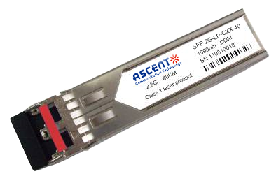
2.5G SFP CWDM 40 km
SFP-2G-LP-CXX-40 2.5 Gbps CWDM Single-mode SFP Transceiver
2.5G SFP BiDi 10 km
SFP-2G-LP-3155-10 2.5 Gb/s BiDi Single-mode SFP Transceiver

2.5G SFP 1310nm 20km
SFP 1310nm 2.5Gbps LX 20km Transceiver
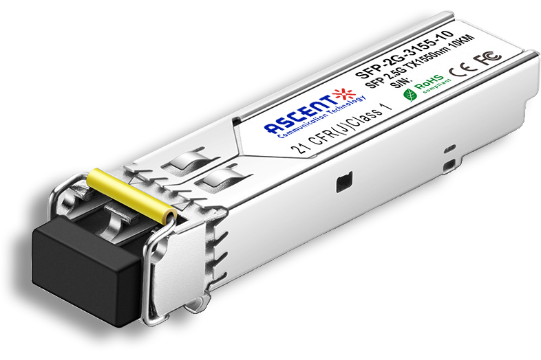
2.5G SFP 1310nm 10km
2.5 Gb/s 1310nm Single-mode SFP Transceiver
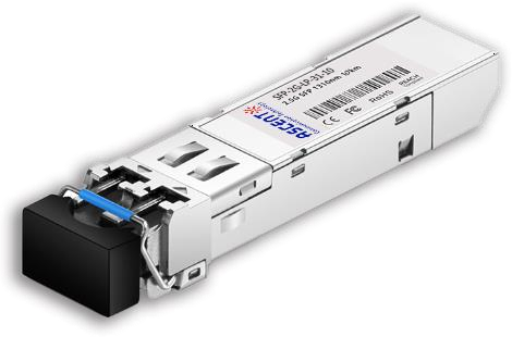
2.5G SFP 1310 nm 2 km
SFP-2G-LP-31-2K 2.5 Gb/s 1310 nm Single-mode SFP Transceiver
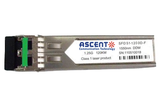
1.25G SFP EZX 1550 nm 120 km
SFP-AGLP-51-120 1.25Gb/s 1550nm Single-mode SFP Transceiver
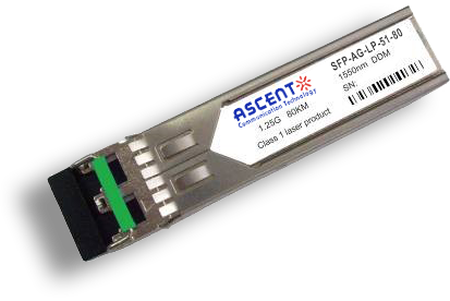
1.25G SFP ZX 1550 nm 80 km
SFP-AG-LP-51-80 1.25 Gb/s 1550 nm Single-Mode SFP Transceiver
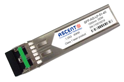
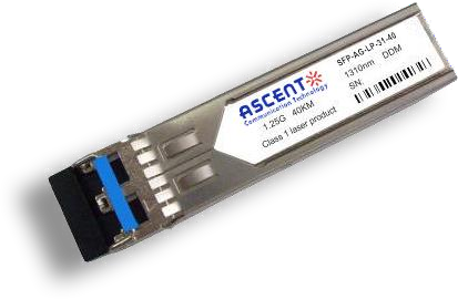
1.25G SFP EX 1550 nm 40 km
SFP-AG-LP-51-40 1.25 Gbps 1550 nm Single-mode SFP Transceiver
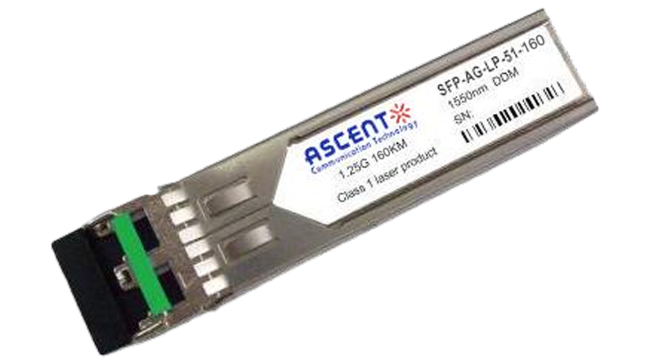
1.25G SFP 1550 nm 160 km
1.25 Gb/s SFP 1550nm 160km Transceiver
1.25G SFP EX 1310 nm 40 km
SFP-AG-LP-31-40 1.25 Gb/s 1310 nm Single-mode SFP Transceiver
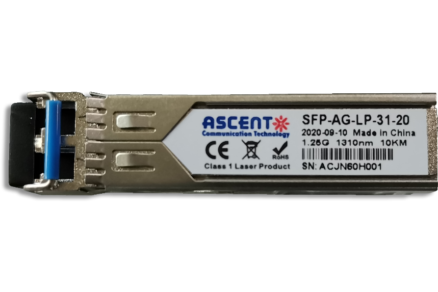
1.25G SFP 1310 nm 20 km
SFPP-AG-LP-31-20 1.25 Gb/s 1310 nm Single-Mode SFP Transceiver

1.25G SFP 1310 nm 10 km
SFPP-AG-LP-31-10 1.25 Gb/s 1310 nm Single-Mode SFP Transceiver

1.25G SFP SR 850 nm 550 m
SFP-AG-LP-85-05 1.25Gb/s 850 nm Multi-Mode SFP Transceiver

1.25G SFP BX 3155 20 km
SFP BIDI 1.25G 1310/1550 nm 20 km DDM
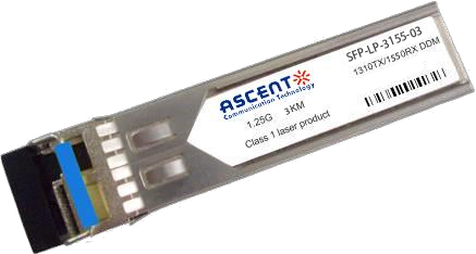
1.25G SFP BX 3155 3 km
SFP BIDI 1.25G 1310/1550 nm 3 km
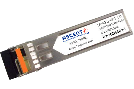
1.25G SFP BX 4950 120 km
SFP-AGLP4955-120 SFP BIDI 1.25G 1490/1550 nm 120 km DDM

1.25G SFP BX 4950 80 km
SFP-AGLP-4955-80 SFP BIDI 1.25G 1490/1550 nm 80 km DDM

1.25G SFP BX 3150 40 km
SFP-AGLP-3155-40 SFP BIDI 1.25G 1310/1550 nm 40 km DDM
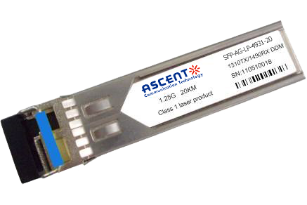
1.25G SFP BX 3149 20 km
SFP-AGLP-3149-20 SFP BIDI 1.25G 1310/1490 nm 20 km DDM

1000M Copper SFP
SFP-AG-CO-01 1000M Copper SFP Transceiver
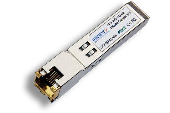
10/100/1000M Copper SFP
SFP-AG-CO-02 10/100/1000M Copper SFP Transceiver

1000M Copper SFP w/ Auto-Negotiation
SFP-AG-CO-03 1000M Auto Adapt Copper SFP Transceiver
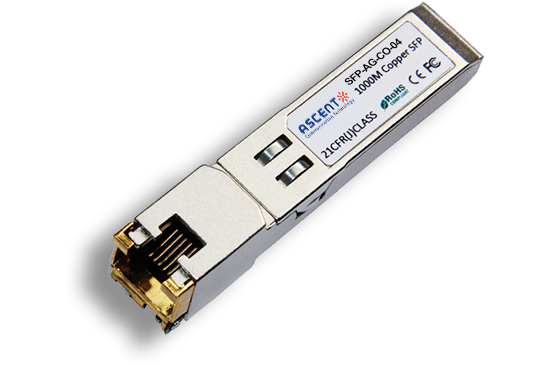
10/100/1000M Copper SFP w/ Link Indicator
SFP-AG-CO-04 10/100/1000M Copper SFP Transceiver w/ Link Indicator
155M SFP 1550 nm 80 km
SFP-AF-LP-51-80 155 Mb/s 1550ô nm Single?Mode SFP Transceiver

155M SFP OC3 1310nm 15 km
SFP_ONS-SI-155-I1 SFP Plug-in, OC3 155Mbps 1310nm Single-mode SFP Optical Transceiver, 15km, LC
White Paper
Press Releases
Briefings 1
Briefings 2
Videos, etc.
QRG
Manual1
Manual2
Get in touch with our experts
Feedback