- FIBER OPTIC TRANSCEIVERS >800G & 400G Transceivers >400G QSFP-DD SR8 850 nm 100 m
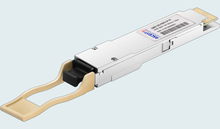
400G QSFP-DD SR8 850 nm 100 m
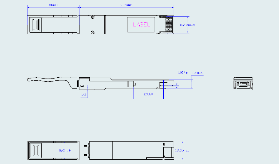
Ascentãs QSFP-DD-LP-01 is a 400 Gb/s Quad Small Form Factor Pluggable-double density (QSFP-DD) optical module designed for short-range optical communication applications. The module is designed to operate over multi-mode fiber systems using a nominal wavelength of 850 nm. The electrical interface uses a 76-pins connector, and the optical interface uses an MPO connector.
ã Compliant with IEEE 802.3cd
ã Supports 400 Gb/s aggregate bit rate
ã Up to 53.125 Gbps data rate per channel
ã Up to 70 m link length on OM3 and 100 m on OM4
ã MPO connector receptacle
ã Case temperature range: 0 ô¯C to +70 ô¯C
ã Power dissipation < 10 W
ã RoHS compliant
Absolute Maximum Ratings
It has to be noted that the operation in excess of any individual absolute maximum ratings might cause permanent damage to this module.
Parameter | Symbol | Min. | Typ. | Max. | Unit | Notes |
Storage Temperature | TS | ã40 | +85 | ô¯C | ||
Relative Humidity | RH | 5 | 85 | % | ||
Power Supply Voltage | VCC | ã0.4 | 3.6 | V |
Recommended Operating Conditions
Recommended operating environment specifies parameters for which the electrical and optical characteristics hold unless otherwise noted.
Parameter | Symbol | Min. | Typ. | Max. | Unit | Notes |
Operating Case Temperature | TC | 0 | ã | +70 | ô¯C | |
Supply Voltage | VCC | 3.135 | 3.3 | 3.465 | V | |
Supply Current | ICC | 2730 | mA | |||
Bit Rate | BR | 400 | Gbps | |||
Data Rate, Each Lane | 26.5625 | GBd | ||||
Data Rate Accuracy | ã100 | 100 | ppm | |||
Fiber Length (OM3 MMF) | 70 | m | ||||
Fiber Length (OM4 MMF) | 70 | m |
Optical Characteristics
Parameter | Symbol | Min | Typ. | Max | Unit | Notes |
Transmitter | ||||||
Modulation Format | PAM4 | |||||
Signaling Rate, Each Lane (Range) | 26.5625 ôÝ 100 ppm | GBd | ||||
Center Wavelength | ö£0 | 840 | 860 | nm | ||
Spectral Width (RMS) | ü | 0.6 | nm | 1 | ||
Average Launch Power, Each Lane | ã6 | 4 | dBm | |||
Outer Optical Modulation Amplitude (OMAouter), Each Lane | ã4.0 | 3 | dBm | 2 | ||
Launch Power in OMAouter ã TDECQ | ã5.9 | dBm | ||||
Transmitter and Dispersion Eye Closure (TDECQ), Each Lane | TDECQ | 4.9 | dBm | |||
Average Launch Power of OFF Transmitter, Each Lane | ã30 | dBm | ||||
Extinction Ratio, Each Lane | ER | 3 | dB | |||
Optical Return Loss Tolerance | ORL | 12 | dB | |||
Receiver | ||||||
Modulation Format | PAM4 | |||||
Data Rate, Each Lane | 26.5625 ôÝ 100 ppm | GBd | ||||
Receiver Wavelength | ö£ | 840 | 860 | nm | ||
Damage Threshold | 5 | dBm | 3 | |||
Average Receive Power, Each Lane | ã7.8 | 4 | dBm | 4 | ||
Receive Power (OMAouter), Each Lane | 3 | dBm | ||||
Receiver Reflectance | RR | ã12 | dB | |||
Stressed Receiver Sensitivity (OMAouter), Each Lane | RSENS | ã3 | dBm | |||
Receiver Sensitivity (OMAouter), Each Lane (Max.) | RS = max(ã6.5, SECQ ã 7.9) | dB | 5 | |||
Difference in Launch Power between any Two Lanes (OMAouter) | 4.6 | dBm | ||||
Conditions of Stressed Receiver Sensitivity Test | ||||||
Stressed Eye Closure for PAM4 (SECQ), Lane under Test | 4.9 | dB | 6 | |||
OMAouter of Each Aggressor Lane | 3 | dBm | 6 | |||
Notes:
1. RMS spectral width is the standard deviation of the spectrum
2. Even if the TDECQ < 1.9 dB, the OMA (min) must exceed this value.
3. The receiver shall be able to tolerate, without damage, continuous exposure to an optical input signal having this average power level on one lane. The receiver does not have to operate correctly at this input power.
4. Average receive power, each lane (min) is informative and not the principal indicator of signal strength. A received power below this value cannot be compliant; however, a value above this does not ensure compliance.
5.Receiver sensitivity is informative and is defined for a transmitter with a value of SECQ.
6. These test conditions are for measuring stressed receiver sensitivity. They are not characteristics of the receiver.
Electrical Characteristics
Parameter | Symbol | Min | Typ. | Max | Unit | Notes |
Supply Voltage | VCC | 3.135 | 3.3 | 3.465 | V | |
Supply Current | Icc | 2730 | mA | |||
Transmitter | ||||||
Input Differential Impedance | Rin | 100 | öˋ | 1 | ||
Differential Data Input Swing | Vin,pp | 400 | 900 | mV | ||
Receiver | ||||||
Differential Data Output Swing | Vout,pp | 900 | mV | 2 | ||
Notes
1. Connected directly to TX data input pins.
2. In to 100 öˋ differential termination
Digital Diagnostic Monitoring Information
Parameter | Accuracy | Calibration |
Temperature | ôÝ3 ô¯C | Internal |
Voltage | ôÝ3 % | Internal |
Bias Current | ôÝ10 % | Internal |
TX Power | ôÝ3 dB | Internal |
RX Power | ôÝ3 dB | Internal |

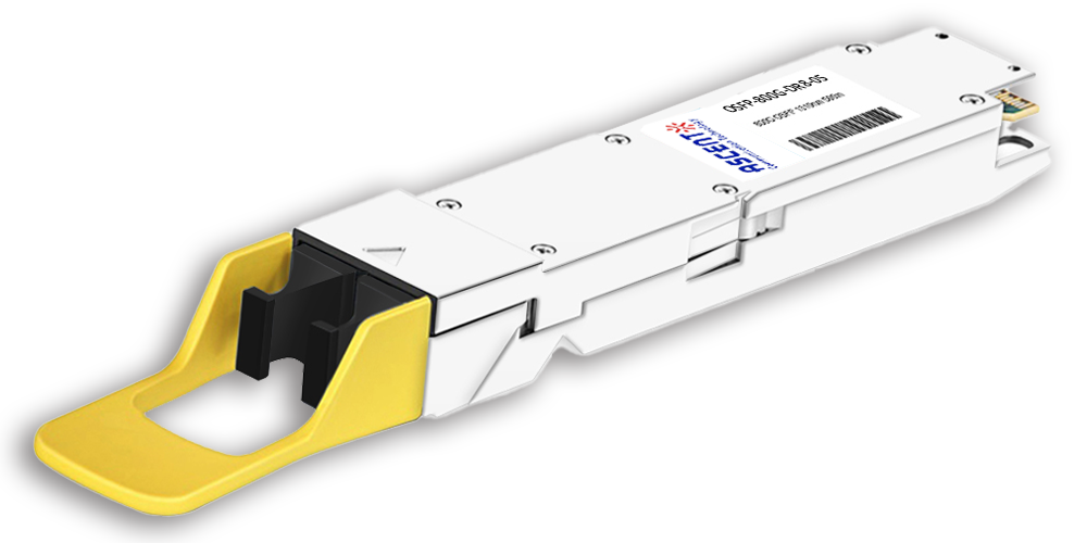
800G OSFP DR8 1310 nm 500 m
800 Gb/s DR8 OSFP 500m Optical Transceiver
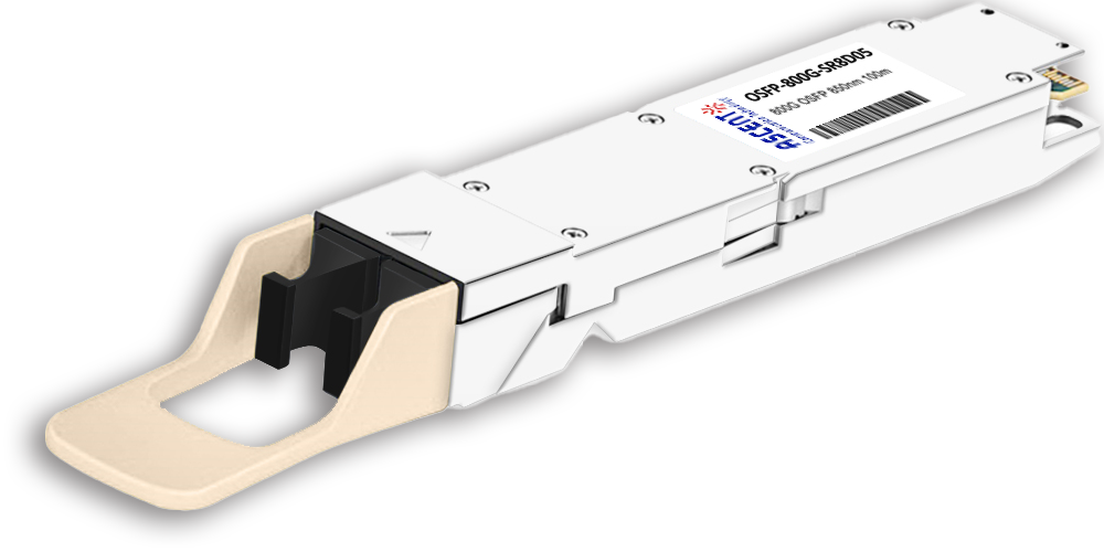
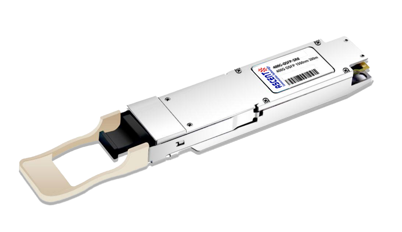
800G OSFP SR8 850 nm 100 m
OSFP-800G-SR8D-01 800 Gb/s OSFP SR8 850 nm 100 m Transceiver
400G QSFP56-DD 10km
400G QSFP-DD 4X100G LR1 Optical Transceiver
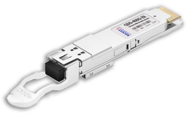
400G QSFP-DD ZR+
QSFP-DD-ZR-80 400 Gb/s QSFP-DD 80 km Transceiver
400G QSFP-DD ER8 40 km
QSFP-DD-ER8-40 400 Gb/s QSFP-DD 40 km Transceiver
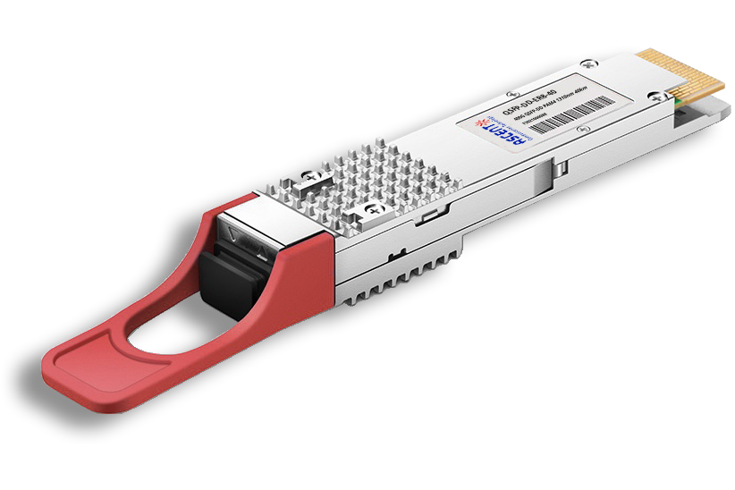
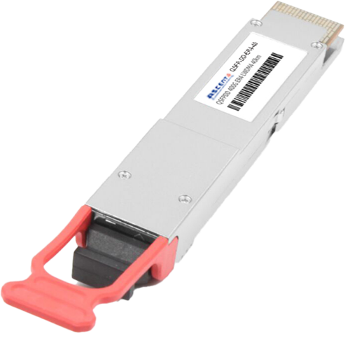
400G QSFP-DD 30 km
400 Gb/s QSFP-DD 30 km Transceiver
400G QSFP-DD 40 km
400 Gb/s QSFP-DD 40 km Transceiver
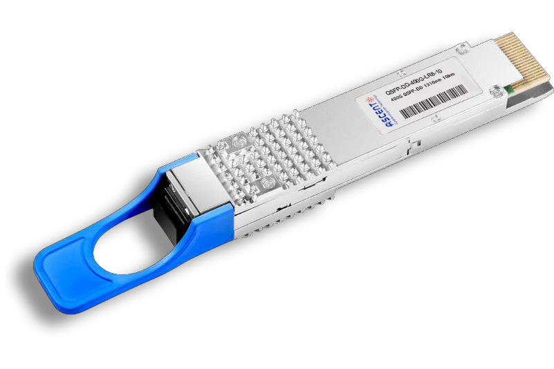
400G QSFP-DD LR8 1310 nm 10 km
QSFP-DD-LR8-10 400 Gb/s QSFP-DD LR8 10 km Transceiver

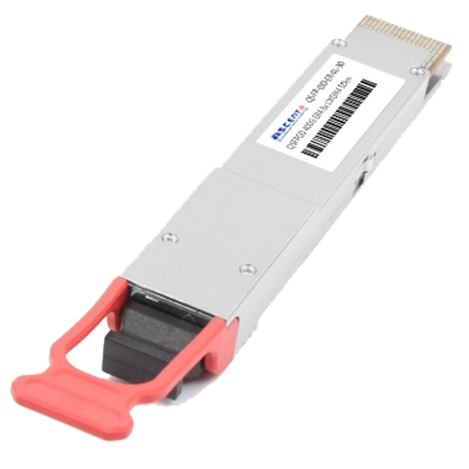
400G QSFP-DD LR4 CWDM 10 km
QSFP-DD-LR4-10 400 Gb/s QSFP-DD LR4 CWDM 10 km Transceiver
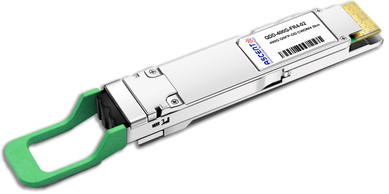
400G QSFP-DD FR4 2km
400 Gb/s QSFP-DD FR4 2 km DDM Transceiver
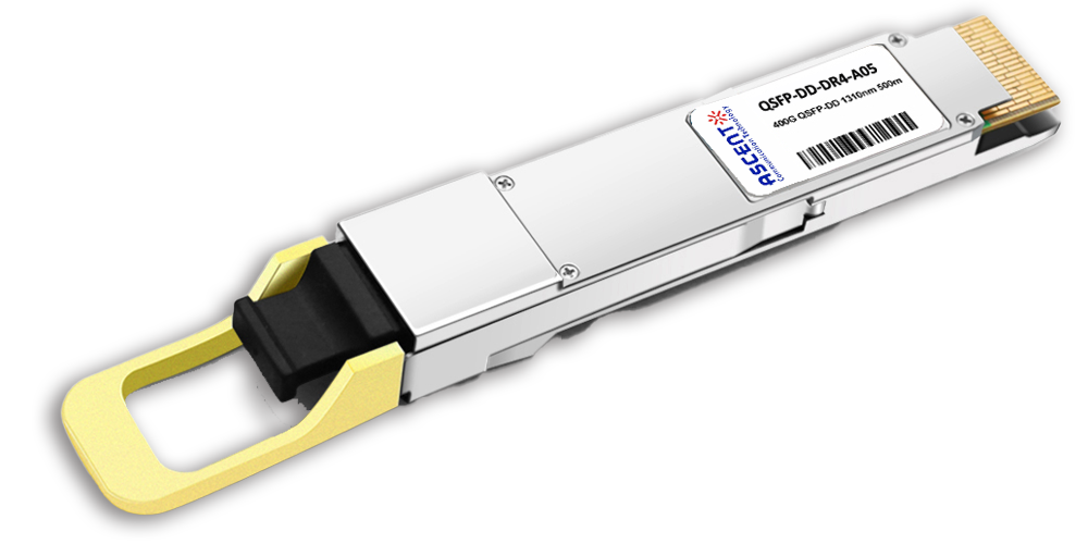
400G QSFP-DD DR4 500m
400 Gb/s QSFP-DD DR4 500m Transceiver
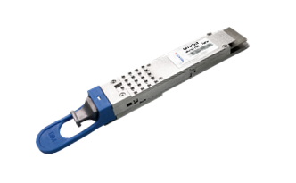
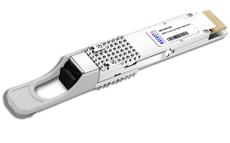
400G QSFP-DD DCO ZR
400G QSFP-DD DCO ZR Coherent Optical Transceiver
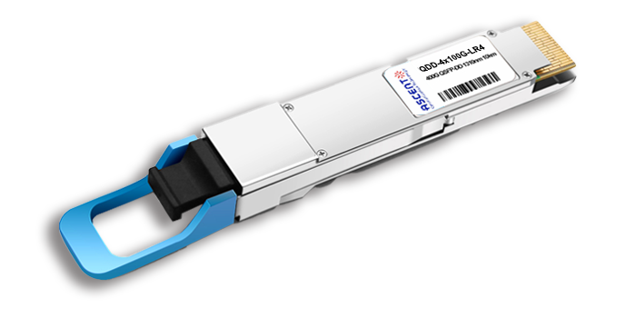
4X100G QSFP-DD LR4 10km
QDD 4x100G 1310nm LR 10 km Transceiver
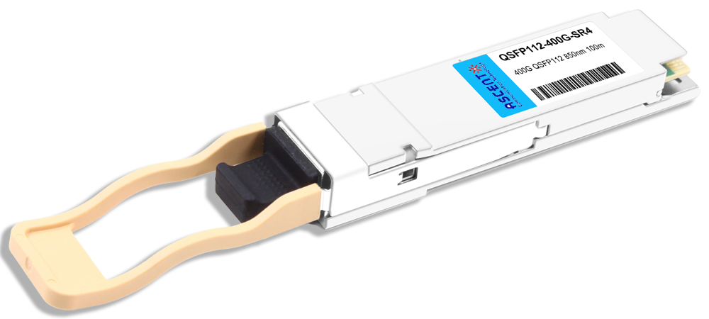
400G QSFP112 SR4 850 nm 100 m
QSFP112-400G-SR4-01 400 Gb/s QSFP112 SR4 850 nm 100 m Transceiver
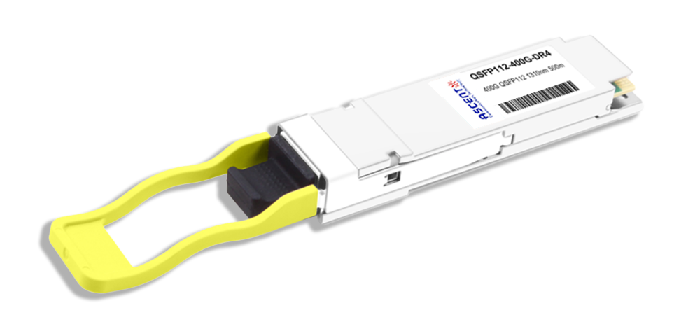
400G QSFP112 DR4 1310 nm 500 m
400G QSFP112 DR4 1310 nm Transceiver 500m
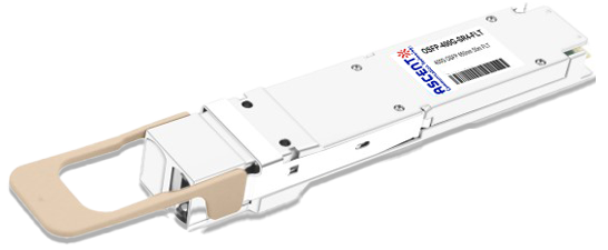
400G OSFP SR4 FLT 50m Transceiver
400 Gbps Multi-Mode 50m OSFP Transceiver
400G OSFP SR8 100m Transceiver
400 Gbps PSM8 Multi-Mode 100m OSFP Transceiver
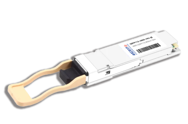
400G QSFP112 VR4 Transceiver
400G QSFP112 VR4
White Paper
Press Releases
Briefings 1
Briefings 2
Videos, etc.
QRG
Manual1
Manual2
Get in touch with our experts
Feedback