- FIBER OPTIC TRANSCEIVERS >10G Transceivers >10G SFP+ LR 1310 nm 20 km
10G SFP+ LR 1310 nm 20 km
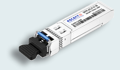
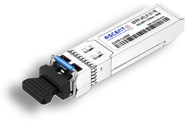
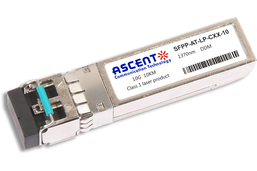
ASCENTãs SFPP-ATLP-31-20 Small Form Factor Pluggable (SFP) transceivers are compatible with the Small Form Factor Pluggable Multi-Sourcing Agreement (MSA). The transceiver consists of five sections: the LD driver, the limiting amplifier, the digital diagnostic monitor, the 1310nm FP laser and the PIN photo-detector. The module data link up to 20 km using 9/125 ôçm single-mode fiber. The optical output can be disabled by a TTL logic high-level input of Tx Disable, and the system also can disable the module via I2C. Tx Fault is provided to indicate that degradation of the laser. Loss Of signal (LOS) output is provided to indicate the loss of an input optical signal of receiver or the link status with partner. The system can also get the LOS (or Link)/Disable/Fault information via I2C register access. The metal housing ensures low EMI interference standards, with connector retainer.
ã Up to 11.32 Gbps Data Links
ã Up to 20 km transmission on SMF
ã 1310 nm DFB Laser and PIN/TIA receiver
ã Metal enclosure, for lower EMI
ã 2-wire interface with integrated Digital Diagnostic monitoring
ã Hot-pluggable SFP+ footprint
ã Compliant with SFP+ MSA with LC connector
ã Single 3.3 V power supply
ã Case operating temperature range: 0ô¯C to 70ô¯C
ã Power dissipation < 1.2 W
ã 10GBASE-LR/LW & 10G Ethernet
ã Compliant with SFF-8431
ã Compliant with SFF 8472
ã RoHS compliant
Absolute Maximum Ratings
Parameter | Symbol | Min. | Typ. | Max. | Unit | Note |
Storage Temperature | TS | ã40 | 85 | ô¯C | ||
Storage Ambient Relative Humidity | HA | 0 | 85 | % | ||
Power Supply Voltage | VCC | ã0.5 | 4 | V | ||
Signal Input Voltage | ã0.3 | Vcc+0.3 | V | |||
Receiver Damage Threshold | +3 | dBm | ||||
Lead Soldering Temperature/Time | TSOLD | 260/10 | ô¯C/sec | 1 | ||
Lead Soldering Temperature/Time | TSOLD | 360/10 | ô¯C/sec | 2 |
Notes
1. Suitable for wave soldering.
2. Only for soldering by iron.
Recommended Operating Conditions
Parameter | Symbol | Min. | Typ. | Max. | Unit | Note |
Case Operating Temperature | Tcase | 0 | 70 | ô¯C | Commercial Industrial | |
Ambient Humidity | HA | 5 | 70 | % | Nonãcondensing | |
Data Rate | 10.3125/10.3125 | Gbps | TX Rate/RX Rate | |||
Transmission Distance | 20 | km | ||||
Coupled Fiber | Singleãmode fiber | 9/125 ôçm G.652 | ||||
Optical Characteristics
Parameter | Symbol | Min. | Typ. | Max. | Unit | Note |
Transmitter | ||||||
Average Output Power | POUT | ã8.2 | +0.5 | dBm | ||
Extinction Ratio | ER | 3 | dB | |||
Center Wavelength | ö£C | 1290 | 1310 | 1330 | nm | DFB Laser |
Side Mode Suppression Ratio | SMSR | 30 | dBm | DFB Laser | ||
Spectrum Width (RMS) | ü | 1 | nm | |||
Transmitter OFF Output Power | POff | ã30 | dBm | |||
Output Eye Mask | Compatible with IEEE 802.3ae | |||||
Receiver | ||||||
Input Optical Wavelength | ö£IN | 1260 | 1600 | nm | ||
Rx Sensitivity | RSENS1 | ã15 | dBm | 1 | ||
Rx Sensitivity (OMA) | RSENS2 | ã10.3 | dBm | 2 | ||
Input Saturation Power (Overload) | PSAT | ã3 | dBm | |||
Loss of Signal Assert | PA | ã30 | dBm | |||
Loss of Signal Deãassert | PD | ã15.4 | dBm | |||
LOS Hysteresis | PDãPA | 0.5 | 6 | dB | ||
Notes:
1. With worstãcase extinction ratio. Measured with a PRBS 231ã1 test pattern, @10.3125 Gb/s, BER < 10ã12.
2. Valid between 1260 nm and 1355 nm. Per IEEE 802.3ae.
Digital Diagnostic Memory Map

Digital Diagnostic Monitoring Information
Parameter | Unit | Accuracy |
Case Temperature | ô¯C | ôÝ3 |
Supply Voltage | V | ôÝ3% |
Tx Bias Current | mA | ôÝ10% |
Tx Optical Power | dB | ôÝ3 |
Rx Optical Power | dB | ôÝ3 |
Electrical Interface Characteristics
Parameter | Symbol | Min. | Typ. | Max. | Unit | Note |
Supply Voltage | VCC | 3.1 | 3.3 | 3.5 | V | |
Supply Current | ICC | 200 | 285 | mA | ||
Transmitter | ||||||
Input Different Impedance | Rin | 90 | 100 | 110 | öˋ | 1 |
SingleãEnded Data Input Swing | Vin, pp | 180 | 700 | mV | ||
Transmitter Disable Voltage | VDIS | 2 | VCC | V | ||
Transmitter Enable Voltage | VEN | 0 | 0.8 | V | ||
Receiver | ||||||
Output Difference Impedance | Rout | 90 | 100 | 110 | öˋ | 1 |
SingleãEnded Data Output Swing | Vout, pp | 300 | 850 | mV | 2 | |
LOS Asserted | VLOSA | 2 | VCCHOST | V | 3 | |
LOS DeãAsserted | VLOSD | 0 | 0.8 | V | 3 | |
Notes:
1. Connected directly to TX data input pins. AC coupled thereafter.
2. Into 100 öˋ differential termination.
3. Loss Of Signal is LVTTL. Logic ã0ã indicates normal operation; logic ã1ã indicates no signal detected.

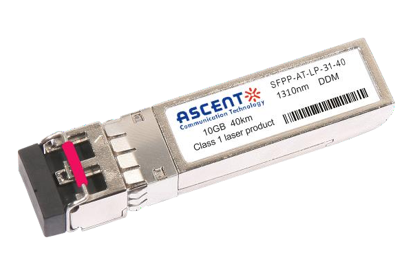
10G SFP+ LR 1310 nm 40 km
10 Gb/s 1310nm SFP+ 40 km Transceiver
10G SFP+ LR 1310 nm 10 km
SFPP-ATLP-31-10 SFP+ Plug-in, 10Gbps, 10km, TX=1310/RX wide, on two single mode fibers, LC/PC Blue

10G SFP+ LRM 1310 nm 2 km
SFPP-ATLP-31-02 10Gb/s 1310nm SFP+ 2 km Transceiver
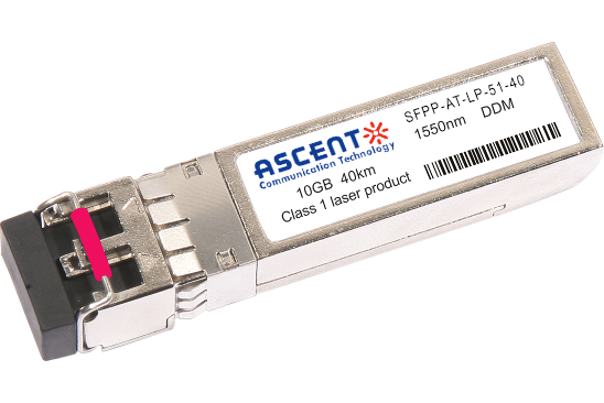
10G SFP+ ER 1550 nm 40 km
SFPP-ATLP-51-40 10 Gb/s 1550 nm SFP+ 40 km Transceiver
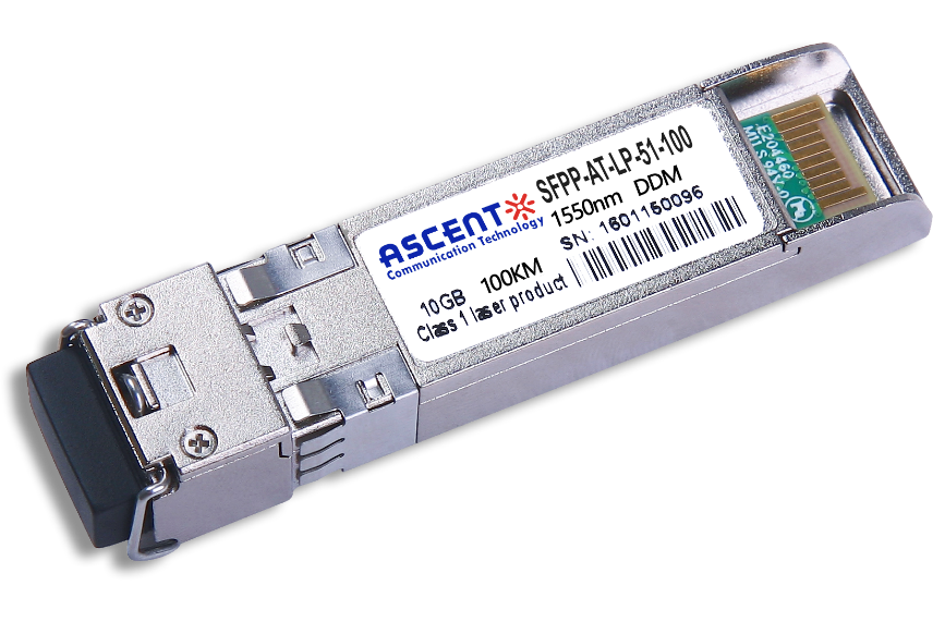
10G SFP+ CDR 1550 nm 100 km
SFPP-ATLP-51-100 10 Gb/s 1550 nm SFP+ 100 km Transceiver
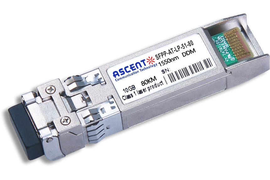
10G SFP+ ZR 1550 nm 80 km
SFPP-ATLP-51-80 10 Gb/s 1550 nm SFP+ 80 km Transceiver
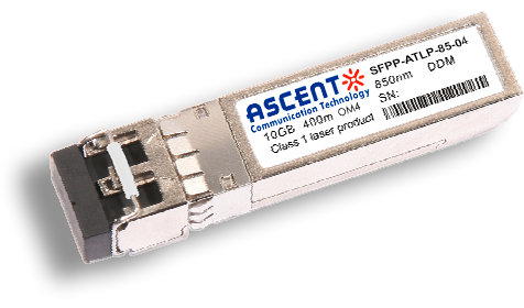
10G SFP+ 850 nm 400 m
10 Gb/s 850nm Multi-mode SFP+ Transceiver 400m
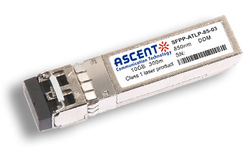
10G SFP+ 850 nm 300 m
SFPP-ATLP-85-03 10 Gb/s 850nm Multi-Mode SFP+ Transceiver
10G SFP+ Tunable DWDM 80 km
SFPP-LP-T99R-80 10 Gb/s Tunable DWDM SFP+ 80 km Transceiver
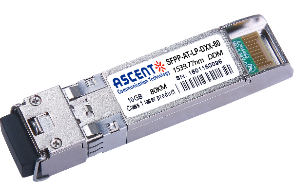
10G SFP+ DWDM 80 km
SFPP-ATLP-DXX-80 10 Gb/s DWDM SFP+ 80 km Transceiver
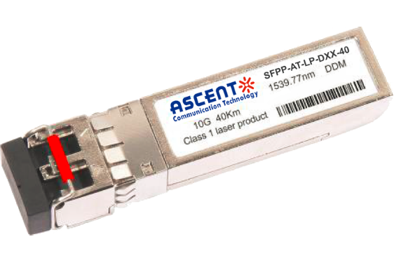
10G SFP+ DWDM 40 km
SFPP-ATLP-DXX-40 SFP+ Plug-in, 10Gbps, 40km, TX=ITU Ch xx (17 to 61) /RX wide, on two single mode fibers, LC/PC Blue
10G SFP+ CWDM 80 km
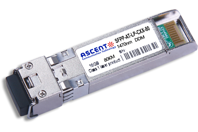
SFPP-ATLP-CXX-80 SFP+ Plug-in, 10 Gbps, 80 km, TX = CWDM Ch xx (1470ô nm to 1610 nm)/RX wide, on two single-mode fibers, LC/PC Blue.
10G SFP+ CWDM 2733 60 km
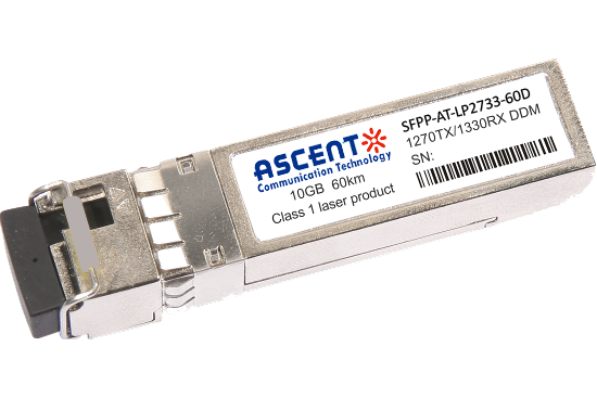
SFPP-AT-LP-XXXX-60D 10 Gb/s BIDI SFP+ 60 km Transceiver
10G SFP+ CWDM 40 km
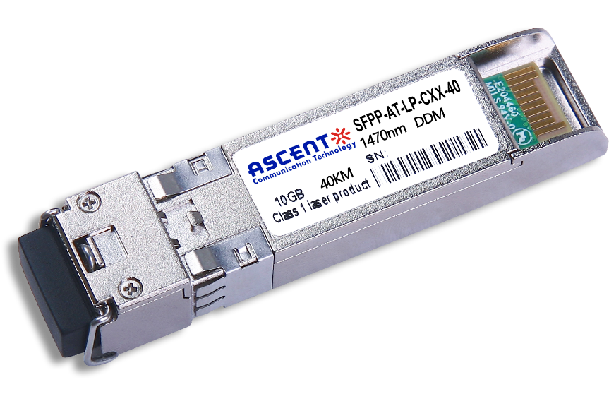
SFPP-ATLP-CXX-40 SFP+ Plug-in, 10Gbps, 40km, TX=CWDM Ch xx (1270ô nm to 1610 nm) /RX wide, on two single mode fibers, LC/PC Blue
10G SFP+ CWDM 10 km
10 Gb/s CWDM SFP+ 10 km Transceiver
10G SFP+ Single mode CWDM 10 km
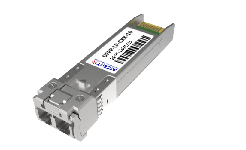
SFPP-ATLP-CXX-10 SFP+ Plug-in, 10 Gbps, 10 km, TX=CWDM Ch xx (1270 nm to 1610 nm)/RX wide, on two single-mode fibers, LC/PC Blue
10G SFP+ CWDM 4955 80 km
SFP+ BIDI 10 Gb/s 1490/1550 nm 80 km Transceiver
10G SFP+ CWDM 2733 40 km
SFPP-AT-LP-XXXX-40 SFP+ Plug-in, 10Gbps, 40km, TX=1270/RX=1330 , on one single mode fibers, LC/PC Blue
10G SFP+ CWDM 2733 10 km
SFPP-LP-XXXX-10 SFP+ Plug-in, 10Gbps, 10km, TX=1270/RX=1330 , on one single mode fibers, LC/PC Blue

10G XFP BIDI 80KM
XFP 10 Gb/s BIDI Single-Mode 80 km Transceiver DDM

10G XFP BIDI 40KM
XFP 10 Gb/s BIDI Single-Mode 40 km Transceiver DDM

10G XFP BIDI 20KM
XFP 10 Gb/s BIDI Single-Mode 20 km Transceiver DDM

10G XFP BIDI 10KM
XFP 10 Gb/s BIDI Single-Mode 10 km Transceiver DDM

10G XFP LR 1310 nm 20 km
XFP-AT-LP-31-20 10 Gb/s 20 km XFP Transceiver

10G XFP LR 1310 nm 10 km
XFP-AT-LP-31-10 10 Gb/s 10 km XFP Transceiver
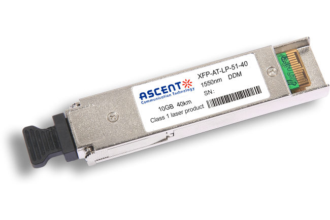
10G XFP ER 1550 nm 40 km
XFP-AT-LP-51-40 10 Gb/s 40 km XFP Optical Transceiver

10G XFP ZR 1550 nm 80 km
XFP-AT-LP-51-80 10 Gb/s 80 km XFP Optical Transceiver
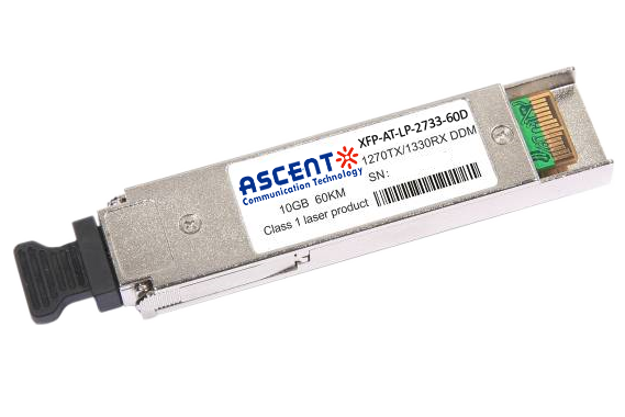
10G XFP CWDM 2633 60 km
XFP-ATLP-XXXX-60 10 Gb/s BIDI XFP 60 km Transceiver
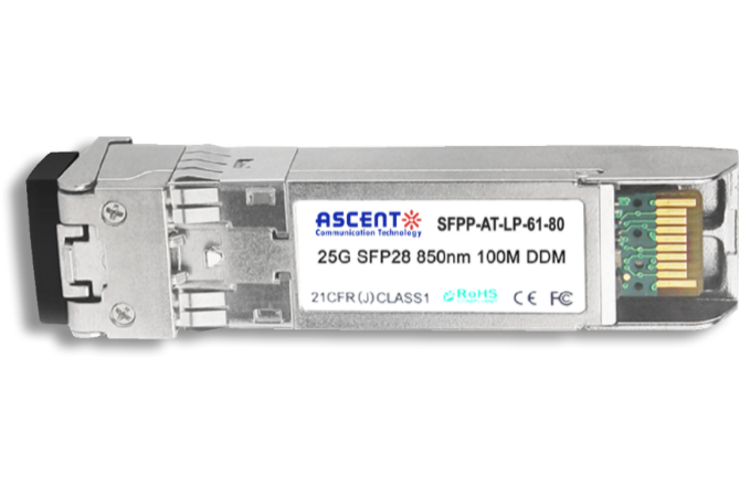
10G SFP+ CWDM 1610 80 km
SFPP-ATLP-61-80 SFP+ Plug-in, 10Gbps, 80km, TX=1610/RX wide, on two single mode fibers, LC/PC Blue
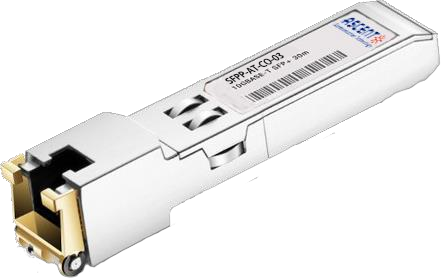
10G SFP+ Copper RJ45 30 m
SFPP-AT-CO-03 10GBASE-T SFP+ Copper RJ45 30m Transceiver

10G X2 850nm 300m
X2 10Gb/s 850nm Multi-mode Transceiver 300m
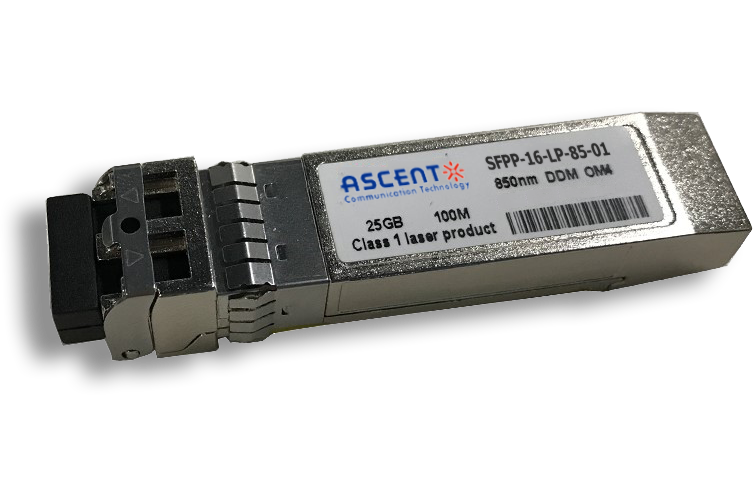
16G SFP+ FC 850 nm 100 m
SFPP-16-LP-85-01 16 Gb/s 850 nm SFP+ 100 m Transceiver
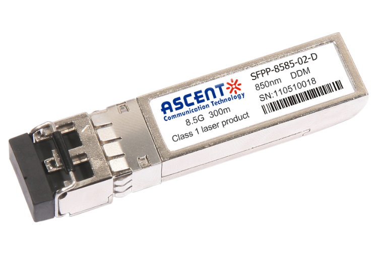
8.5G SFP+ SR 850 nm 150 m
SFPP-A8LP-85-015 8.5 Gb/s 850 nm Multi-Mode SFP+ Transceiver
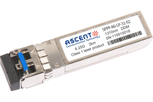
6.25G SFP+ LRM 1330 nm 2 km
SFPP-A6-LP-31-02 6.25 Gb/s Single-Mode SFP+ Transceiver
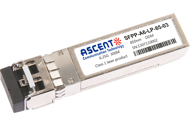
6.25G SFP+ SR 850 nm 300 m
SFPP-A6-LP-85-03 6.25 Gb/s 850 nm Multi-Mode SFP+ Transceiver
White Paper
Press Releases
Briefings 1
Briefings 2
Videos, etc.
QRG
Manual1
Manual2
Get in touch with our experts
Feedback