- FIBER OPTIC TRANSCEIVERS >200G & 100G Transceivers >100G QSFP28 ER4-E 1310 nm 40 km
100G QSFP28 ER4-E 1310 nm 40 km
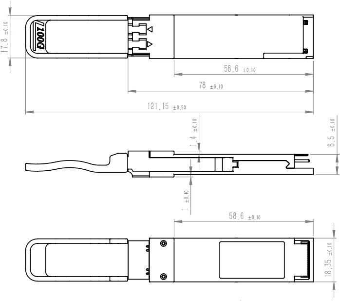
Ascent’s 100G QSFP28 ER4-E is designed for 40km optical communication applications. This module contains 4-lane optical transmitter, 4-lane optical receiver and module management block including 2 wire serial inter-face. The optical signals are multiplexed to a single-mode fiber through an industry standard LC connector. Ascent’s 100G QSFP28 ER4-E Optical Transceiver offers service providers, network operators 100 Gigabit Ethernet connectivity options for data center networking, enterprise core aggregation, and service provider transport applications. It integrates receiver and transmitter path on one module. In the transmit side, four lanes of serial data streams are recovered, retimed, and passed to four laser drivers. The laser drivers control 4-EML with center wavelength of 1296 nm, 1300nm, 1304nm and 1309 nm. The optical signals are multiplexed to a single–mode fiber through an industry standard LC connector. In the receive side, the four lanes of optical data streams are optically de-multiplexed by the integrated optical de- multiplexer. Each data stream is recovered by a APD and trans-impedance amplifier, retimed. This module features a hot-pluggable electrical interface, low power consumption and 2-wire serial interface. This product is designed with form factor, optical/electrical connections, and digital diagnostic interface according to the QSFP28 Multi-Source Agreement (MSA) and compliant to IEEE 802.3bm.
Support line rates from103.125 Gb/s
Transmission data rate up to 25.78125Gbps per channel
LAN WDM EML laser and APD
QSFP28 MSA package with duplex LC connector
Single +3.3V Power Supply
Low Power Consumption
Complies with EU Directive 2015/863/EU
Absolute Maximum Ratings
Parameter Storage Temperature | Symbol Ts | Min. -40 | Max. 85 | Unit °C |
Maximum Supply Voltage | VCC | -0.5 | 3.6 | % |
Operating Relative Humidity | RH | 85 | V |
Recommended Operating Conditions
Parameter Operating Case Temperature | Symbol TC | Min. 0 | Typ. | Max. +70 | Unit °C | Note |
Power Supply Voltage | VCC | 3.13 | 3.3 | 3.47 | V | |
Power Supply Current | ICC | - | 1.51 | A | ||
Maximum Power Consumption | PD | 5 | W | |||
Aggregate Bit Rate BRAVE | 103.125 | Gb/s | ||||
Lane Bit Rate BRLANE | 25.78125 | Gb/s | ||||
Transmission Distance TD | 40 | km | ||||
Coupled Fiber Single-mode fiber | 9/125 µm SMF | |||||
Optical Characteristics | ||||||
Parameter | Symbol | Min. | Typ. | Max. | Unit | Notes |
Transmitter | ||||||
Signaling Speed per Lane | 25.78125 | Gb | ||||
Lane Wavelength | L0 | 1294.53 | 1295.56 | 1296.59 | nm | |
L1 | 1299.02 | 1300.05 | 1301.09 | nm | ||
L2 | 1303.54 | 1304.58 | 1305.63 | nm | ||
L3 | 1308.09 | 1309.14 | 1310.19 | nm | ||
Total Average Launch Power | PT | 12.5 | dBm | 1 | ||
Average Launch Power per | Pavg | -1 | 6.5 | dBm | 1 | |
Lane, | ||||||
OMA, each Lane | POMA | 0.5 | 6.5 | dBm | 1 | |
Difference in Launch Power between any Two | Ptx, diff | 3 | dB | |||
Lanes(Average and OMA) | ||||||
between Any Two | ||||||
Lanes (OMA) | ||||||
Average Output Power (Laser | Poff | -30 | dBm | |||
Turn Off) | ||||||
Side Mode Suppression Ratio | SMSR | 30 | dB | |||
Extinction Ratio, 100GE | ER | 7 | dB | |||
RIN20OMA | RIN | -130 | dB/Hz | |||
Transmitter Reflectance | RT | -26 | dB | |||
Optical Eye Mask | {0.25,0.4, | 0.45, 0.25, 0.28, | 0.4} | % | 2 | |
Receiver | ||||||
Signaling Rate, each Lane | 25.78125 | Gb | ||||
Center Wavelength Lane 0 | λ0 | 1294.53 | 1295.56 | 1296.59 | nm | |
Center Wavelength Lane 1 | λ1 | 1299.02 | 1300.05 | 1301.09 | nm | |
Center Wavelength Lane 2 | λ2 | 1303.54 | 1304.58 | 1305.63 | nm | |
Center Wavelength Lane 3 | λ3 | 1308.09 | 1309.14 | 1310.19 | nm | |
Parameter | Symbol | Min. | Typ. | Max. | Unit | Notes |
Damage Threshold , each Lane | Pdamage | -2.5 | dBm | |||
Receiver Sensitivity, each Lane | SEN | -18 | dBm | 3 | ||
Los Assert | LosA | -30 | dBm | |||
Los De-assert | LosDA | -22 | dBm | |||
Los Hysteresis | LosH | 0.5 | dB |
Note:
1. The optical power is launched into SMF.
2. Measured with a PRBS 231-1 test pattern @25.78125, Hit ratio≤5E-5.
3. Measured with a PRBS 231-1 test pattern @25.78125 Gb/s, BER≤1E-12.
Electrical Characteristics
Parameter | Symbol | Min | Typ | Max | Unit | Notes |
Transmitter (Module Input) | ||||||
Data Rate, each Lane | 25.78125 | Gbps | ||||
Differential Voltage pk-pk | Vpp | 900 | mV | 1 | ||
Common Mode Voltage | Vcm | -350 | 2850 | mV | ||
Transition Time | Trise/Tf all | 10 | ps | 2 | ||
Receiver (Module Output) | ||||||
Data Rate, each Lane | 25.78125 | Gbps | ||||
Common Mode Noise, RMS | Vrms | 17.5 | mV | |||
Differential Output Voltage Swing | Vout, pp | 900 | mV | |||
Eye Width | EW15 | 0.57 | UI | |||
Eye Height | EH15 | 228 | mV | |||
Differential Termination Resistance Mismatch | 10 | % | 1 | |||
Transition Time | Trise/Tf all | 12 | ps | |||
1. At 1 MHz
2. 20% to 80%.
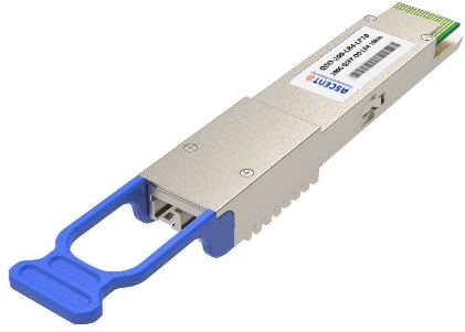
200G QSFP DD LR4 10km
200 Gb/s QSFP DD LR4 10 km Transceiver
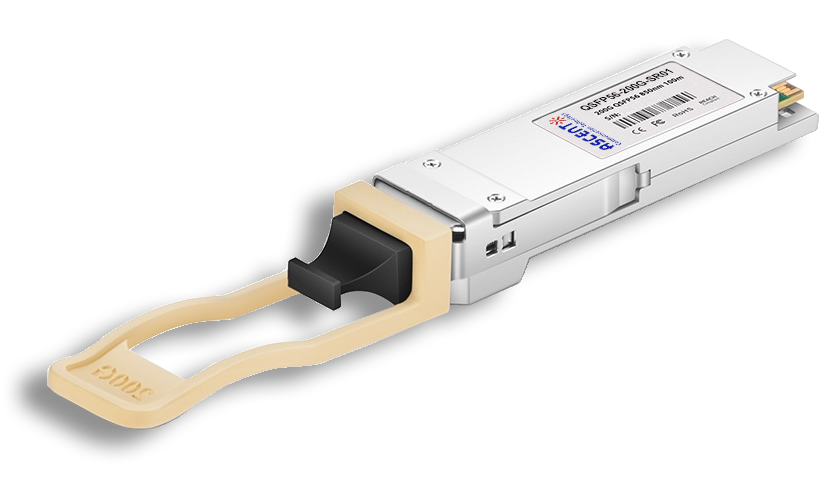
200G QSFP56 SR4 850 nm 100 m
QSFP56-200G-SR01 200 Gb/s QSFP56 SR4 850 nm 100 m Transceiver

100G QSFP28 LX4 2km
100 Gb/s 2km QSFP28 LX4 Transceiver

100G QSFP28OA LR4 10km
100 Gb/s 10 km QSFP28 LR4 Transceiver

100G QSFP28 ZR4 1310 nm 80 km
QSFP28-100G-LP80 QSFP28 100 Gbps ZR4 Transceiver
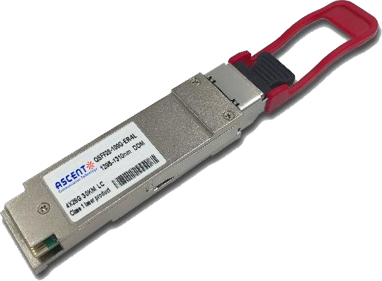
100G QSFP28 ER4L 1310 nm 40 km
QSFP28-100G-LP40 100 Gb/s 40 km QSFP28 ER4 Lite Transceiver
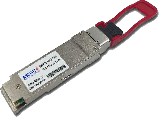
100G QSFP28 ER4 1310 nm 40 km
100 Gb/s 40 km QSFP28 ER4 Transceiver
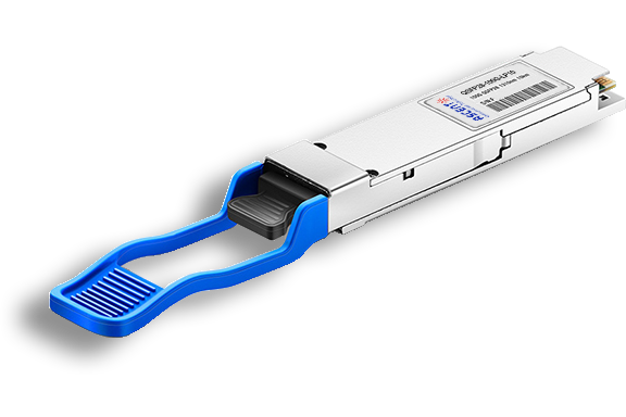
100G QSFP28 LR4 1310 nm 10 km
QSFP28-100G-LP10 100 Gb/s 10km QSFP28 LR4 Transceiver
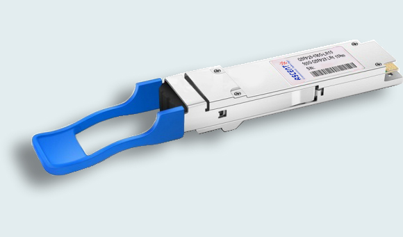
100G QSFP28 LR Single λ 10 km
100G QSFP28 LR1 10 km Single Channel

100G QSFP28 DR Single λ 500 m
QSFP28 100G DR Single Lambda Transceiver
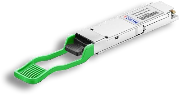
100G QSFP28 CWDM4 1310 nm 2 km
QSFP28-100G-LP02 QSFP28 100 Gbps CWDM4 Transceiver
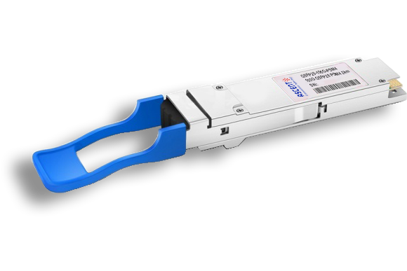
100G QSFP28 PSM4 1310 nm 2 km
QSFP28-100G-PSM4 100 Gb/s 1310 nm 2 km Transceiver
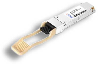
100G QSFP28 SR4 850 nm 100 m
QSFP28-100G-SR01 100 Gb/s SR4 850 nm 100 m Transceiver
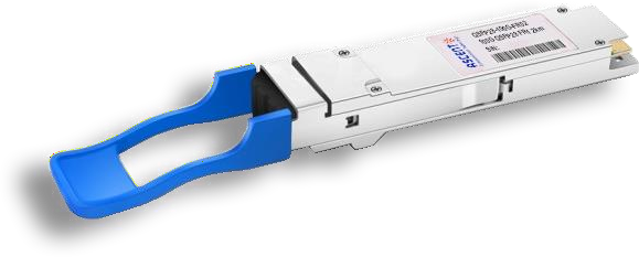
100G QSFP28 FR Single λ 1310 nm 2 km
100G QSFP28 FR 2km Transceiver

100G QSFP28 SR01 BIDI MMF 850nm 100m
QSFP28 BIDI 100 Gb/s SR Transceiver 100m

100G QSFP28 BIDI 80km
QSFP28 BIDI 100 Gb/s ZR4 Transceiver 80km

100G QSFP28 BIDI 40km
QSFP28 BIDI 100 Gb/s ER Transceiver 40km

100G QSFP28 EZR4 100km
QSFP28 100Gb/s EZR4 Transceiver 100km

100G SFP56 ER1 30km
SFP56-DD 100G-ER1 Optical Transceiver 30km

100G SFP56 LR1 10km
SFP56-DD 100G-LR1 Optical Transceiver 10km
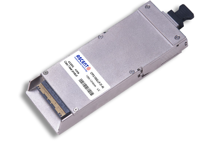
100G CFP2 ER4 40 km
CFP2-LP-31-40 100 Gb/s CFP2 ER4 40 km Transceiver
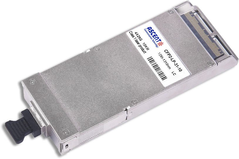
100G CFP2 LR4 10 km
CFP2-LP-31-10 100 Gb/s CFP2 LR4 10 km Transceiver
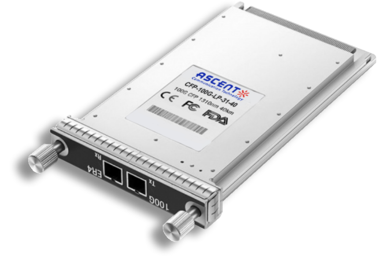
100G CFP ER4 40 km
CFP-LP-31-40 100 Gb/s CFP ER4 40 km Transceiver
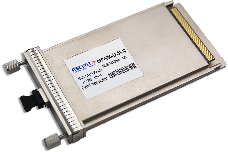
100G CFP LR4 10 km
CFP-LP-31-10 100 Gb/s CFP LR4 10 km Transceiver
White Paper
Press Releases
Briefings 1
Briefings 2
Videos, etc.
QRG
Manual1
Manual2
Get in touch with our experts
Feedback