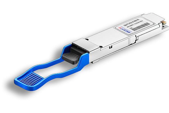
- FIBER OPTIC TRANSCEIVERS >40G & 25G Transceivers >40G QSFP+ CWDM 2 km
40G QSFP+ CWDM 2 km
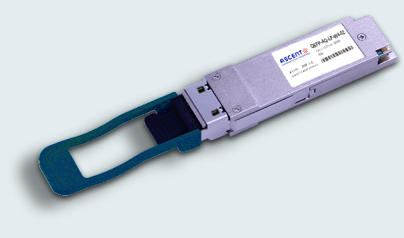
Ascentãs QSFP-AQ-LP-W4-02 is designed to operate over single-mode fiber system using 4X10 CWDM channel in 1310 band and links up to 2km. The module converts 4 inputs channel of 10Gb/s electrical data to 4 CWDM optical signals, and multiplexes them into a single channel for 40Gb/s optical transmission. Reversely, on the receiver side, the module optically de-multiplexes a 40Gb/s input into 4 CWDM channels signals, and converts them to 4 channel output electrical data.
ã 4 CWDM lanes Mux/Demux design
ã Up to 11.1 Gbps data rate per wavelength
ã Up to 2 km transmission on SMF
ã Electrically hot-pluggable
ã Digital Diagnostics Monitoring Interface
ã Compliant with QSFP+ MSA with LC connector
ã Case operating temperature range: 0 ô¯C to +70 ô¯C
ã Power dissipation < 2.5 W
ã Compliant with IEEE 802.3ba
ã Compliant with SFF-8436
ã RoHS compliant
Absolute Maximum Ratings
Parameter | Symbol | Min. | Typ. | Max. | Unit | Note |
Storage Temperature | Ts | ã40 | ã | 85 | ô¯C | |
Relative Humidity | RH | 5 | ã | 95 | % | |
Power Supply Voltage | VCC | ã0.3 | ã | 4 | V | |
Signal Input Voltage | Vccã0.3 | ã | Vcc+0.3 | V | ||
Damage threshold | 3.4 | dBm |
Recommended Operating Conditions
Parameter | Symbol | Min. | Typ. | Max. | Unit | Note |
Case Operating Temperature | Tcase | 0 | ã | 70 | ô¯C | Without air flow |
Power Supply Voltage | VCC | 3.14 | 3.3 | 3.47 | V | |
Power Supply Current | ICC | ã | 760 | mA | ||
Data Rate | BR | 10.3125 | Gbps | Each channel | ||
Transmission Distance | TD | ã | 2 | km | ||
Coupled Fiber | Singleãmode Fiber | 9/125 ôçm SMF | ||||
Optical Characteristics
Parameter | Symbol | Min | Typ. | Max | Unit | Note |
Transmitter | ||||||
Center Wavelength | ö£0 | 1264.5 | 1271 | 1277.5 | nm | |
ö£1 | 1284.5 | 1291 | 1297.5 | nm | ||
ö£2 | 1304.5 | 1311 | 1317.5 | nm | ||
ö£3 | 1324.5 | 1331 | 1337.5 | nm | ||
Total Output Power | POUT | 8.3 | dBm | |||
Average Launch Power per Lane | ã7 | 1 | dBm | |||
Spectral Width | ü | 1 | nm | |||
SMSR | 30 | dB | ||||
Optical Extinction Ratio | ER | 3.5 | dB | |||
Average Launch Power Off per Lane | Poff | ã30 | dBm | |||
Transmitter and Dispersion Penalty per Lane | TDP | 2.3 | dB | |||
RIN | RIN | ã128 | dB/Hz | |||
Output Eye Mask | Compliant with IEEE 802.3ba | |||||
Receiver | ||||||
Rx Sensitivity per Lane | RSENS | ã11.5 | dBm | 1 | ||
Input Saturation Power (Overload) | Psat | 1 | dBm | |||
Receiver Reflectance | Rr | ã26 | dB | |||
Notes:
1. Measured with a PRBS 231ã1 test pattern, @ 10.325 Gb/s, BER<10ã12.
Electrical Characteristics
Parameter | Symbol | Min | Typ. | Max | Unit | Note |
Supply Voltage | Vcc | 3.13 | 3.3 | 3.47 | V | |
Supply Current | Icc | 760 | mA | |||
Transmitter | ||||||
Input Differential Impedance | Rin | 100 | öˋ | 1 | ||
Differential Data Input Swing | Vin, pp | 180 | 1000 | mV | ||
Transmit Disable Voltage | VD | Vccã1.3 | Vcc | V | ||
Transmit Enable Voltage | VEN | Vee | Vee+0.8 | V | 2 | |
Receiver | ||||||
Differential Data Output Swing | Vout, pp | 300 | 850 | mV | 3 | |
LOS Fault | VLOS fault | Vccã1.3 | VccHOST | 4 | ||
LOS Normal | VLOS norm | Vee | Vee+0.8 | 4 |
Notes:
1. Connected directly to TX data input pins. AC coupled thereafter.
2. Or open circuit
3. Into 100 öˋ differential termination.
4. Loss Of Signal is LVTTL. Logic 0 indicates normal operation; logic 1 indicates no signal detected.


64G SFP56 850nm 100m
64 Gb/s SFP56 SW Fibre Channel 850nm Transceiver
40/100G SFP28 SWDM4 100m
40/100Gb/s QSFP28, Bi-Di, Duplex LC 100m Transceiver

40G QSFP+ ER4 Industrial 40 km
40 Gb/s QSFP+ ER4 40 km Transceiver

40G QSFP+ ER4 40 km
40 Gb/s QSFP+ ER4 40 km Transceiver

40G QSFP+ LR4 Industrial 10 km
40 Gb/s QSFP+ LR4 10 km Transceiver

40G QSFP+ LR4 10 km
QSFP-AQ-LP-W4-10 40 Gb/s QSFP LR4 10 km Transceiver

40G QSFP+ PSM4 2 km
40 Gb/s QSFP+ PSM4 Transceiver 2km
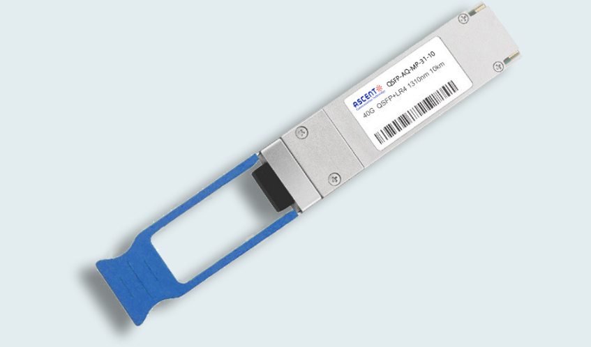
40G QSFP+ PLR4 1310 nm 10 km
QSFP-AQ-MP-31-10 40 Gb/s QSFP+ PSM 1310nm 10km MPO Optical Transceiver

40G QSFP+ CSR4 300m
40 Gb/s 300m QSFP+ CSR4 Transceiver
40GBASE-UNIV QSFP+ MMF and SMF
40G QSFP+ UNIV MMF/SMF 150m/2km
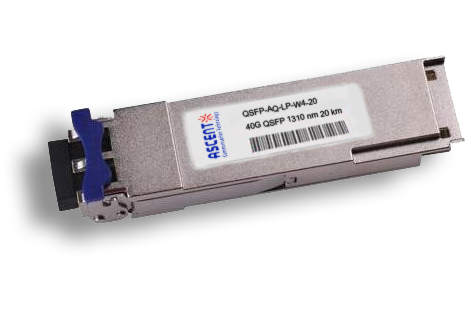
40G QSFP CWDM 20 km
QSFP-AQ-LP-W4-20 40 Gb/s QSFP CWDM 20 km Transceiver
40G QSFP+ BIDI 150m
40 Gb/s QSFP+ BiDi Transceiver 150m
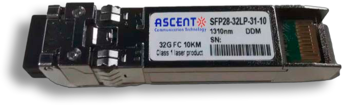
32G SFP28 1310 nm 10 km
32G FC 1310 nm 10 km SFP28 Transceiver

32G SFP28 SR 850 nm 100 m
SFP28-32LP-85-01 32GBASE-SR SFP28 850 nm 100 m DOM Transceiver
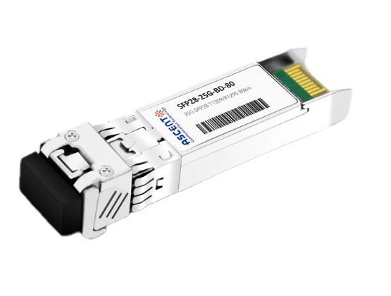
25G SFP28 BIDI 80 km
25G SFP28 BIDI 80 km Transceiver
.png)
25G SFP28 CWDM 10 km(E)
25 Gb/s CWDM EML SFP28 10 km Transceiver
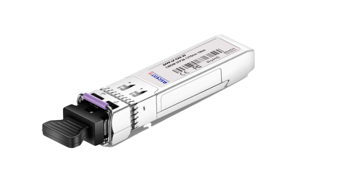
25G SFP28 CWDM 10 km(D)
25 Gb/s CWDM SFP28 10 km Transceiver
25G SFP28 ZR 1310nm 80km
25 Gbps 1310 nm 80 km SFP28 ZR Transceiver
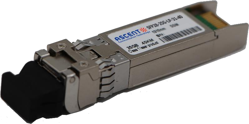
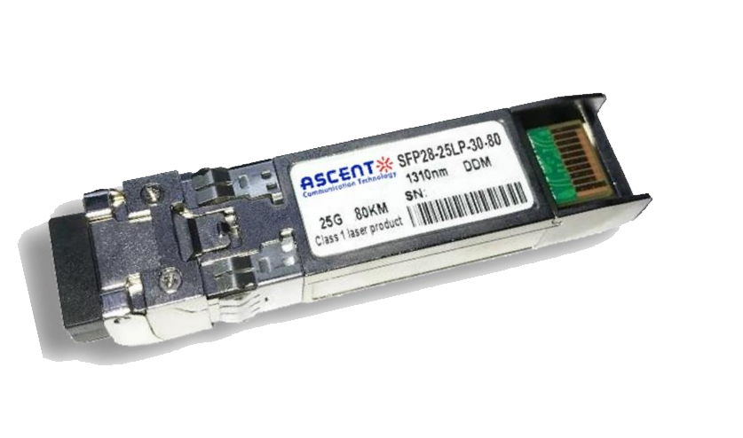
25G SFP28 1310 nm 40km
25 Gb/s 1310 nm Single-Mode SFP28 Transceiver
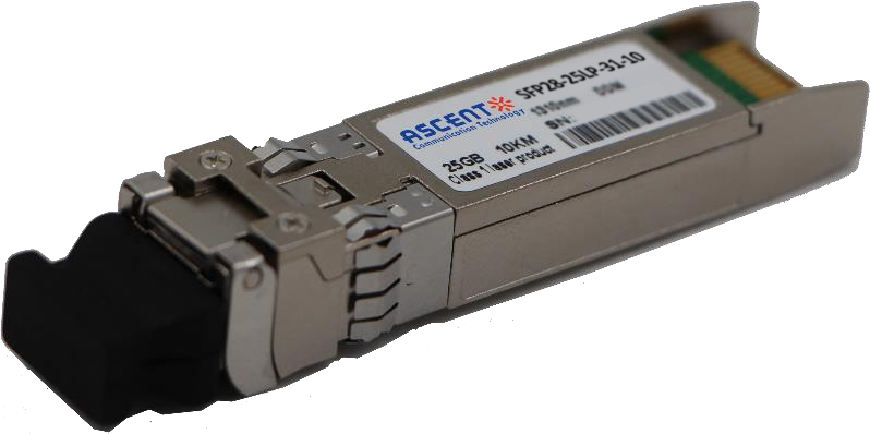
25G SFP28 1310 nm 10 km
SFP28-25LP-31-10 25 Gb/s 1310 nm Single-Mode SFP+ Transceiver
25G SFP28 850 nm 300m
25 Gb/s 850 nm Multi-Mode SFP28 300m Transceiver
25G SFP28 850 nm 100m
SFP28-25LP-85-01 28 Gb/s 850 nm Multi-Mode SFP28 Transceiver

10/25G SFP28 1310nm 40km
10/25 Gb/s SFP28 1310 nm 40km Transceiver
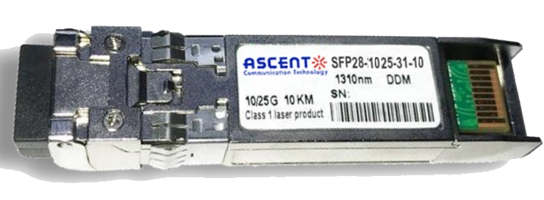
10/25G SFP28 1310nm 10km
10/25 Gb/s SFP28 1310 nm 10km DDM Transceiver

10/25G SFP28 850 nm 300m
10/25 Gb/s SFP28 850 nm 300m Transceiver

10/25G SFP28 850 nm 100m
10/25 Gb/s SFP28 850 nm 100m Transceiver
White Paper
Press Releases
Briefings 1
Briefings 2
Videos, etc.
QRG
Manual1
Manual2
Get in touch with our experts
Feedback