- FIBER OPTIC TRANSCEIVERS >10G Transceivers >10G XFP CWDM 2633 60 km
10G XFP CWDM 2633 60 km
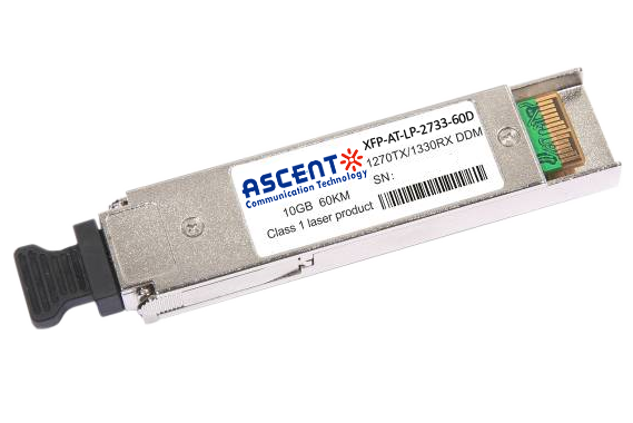
XFP-ATLP-XXXX-60 is a hot pluggable 3.3V small form-factor transceiver module. It is designed expressly for high-speed communications applications that require rates up to 11.3 Gb/s, and is compliant with XFP MSA. The module data link can handle distances up to 60 km with a 9/125 ôçm single-mode fiber.
ã Applicable for 10GBASE-BX 10.3125 Gb/s and 9.953 Gb/s Ethernet networks
ã SONET OC-192 &SDH STM I-64.1
Parameter | Symbol | Value | Notes |
Absolute Maximum Ratings | |||
Storage Temperature | Ts | ã40 ~ 85ô¯C | |
Relative Humidity | RH | 5 ~ 95% | |
Power Supply Voltage | VCC | ã0.3 ~ 4V | |
Signal Input Voltage | Vcc ã 0.3 ~ Vcc + 0.3 | ||
Recommended Operating Conditions | |||
Case Operating Temperature | Tcase | 0 ~ 70ô¯C | Without air flow |
Power Supply Voltage | VCC | 3.14 ~ 3.47V, 3.3V typical | |
Power Supply Current | ICC | 600 mA maximum | |
Data Rate | BR | 9.95 ~ 11.3 Gbps, 10.3125 Gbps typical | |
Transmission Distance | TD | 2 ~ 60 km | |
Coupled Fiber | Singleãmode fiber | ||
Optical Characteristics | |||
Transmitter | |||
Average Launched Power | PO | 0 ~ 5 dBm | |
Average Launched Power(Laser Off) | Poff | ã45 dBm maximum | Note (1) |
Center Wavelength Range | ö£C | 1260 ~ 1280 nm, 1270 nm typical | XFP-AT-LP-2733-60D |
1320 ~ 1340 nm, 1330 nm typical | XFP-AT-LP-2733-60D | ||
Side Mode Suppression Ratio | SMSR | 30 dB minimum | |
Spectrum Bandwidth (ã20 dB) | ü | 1 nm maximum | |
Extinction Ratio | ER | 3.5 dB minimum | Note (2) |
Output Eye Mask | Compliant with IEEE 802.3ae requirements | Note (2) | |
Receiver | |||
Input Optical Wavelength | ö£IN | 1320 ~ 1340 nm, 1330 nm typical | XFP-AT-LP-2733-60D |
1260 ~ 1280 nm, 1270 nm typical | XFP-AT-LP-2733-60D | ||
Receiver Sensitivity | Psen | ã20 dBm maximum | Note (3) |
Input Saturation Power (Overload) | PSAT | ã6 dBm minimum | Note (3) |
LOS ãAssert Power | PA | ã38 dBm minimum | |
LOS ãDeassert Power | PD | ã21 dBm maximum | |
LOS ãHysteresis | PHys | 0.5 ~ 4 dB | |
Electrical Interface Characteristics | |||
Total power supply current | Icc | 600 mA maximum | |
Transmitter | |||
Differential Data Input Voltage | VDT | 120 ~ 820 mVpãp | |
Differential line input Impedance | RIN | 85 ~ 115 ãÎ, 100 ãÎ typical | |
Transmitter Fault OutputãHigh | VFaultH | 2.4V ~ Vcc | |
Transmitter Fault OutputãLow | VFaultL | ã0.3 ~ +0.8V | |
Transmitter Disable Voltageã High | VDisH | 2V ~ Vcc + 0.3 | |
Transmitter Disable Voltageã low | VDisL | ã0.3 ~ +0.8V | |
Receiver | |||
Differential Data Output Voltage | VDR | 300 ~ 850 mVpãp | |
Differential line Output Impedance | ROUT | 80 ~ 120 ãÎ, 100 ãÎ typical | |
Receiver LOS Pull up Resistor | RLOS | 4.7 ~ 10 kãÎ | |
Data Output Rise/Fall time | tr/tf | 20 ps maximum | |
LOS Output VoltageãHigh | VLOSH | 2V ~ Vcc | |
LOS Output VoltageãLow | VLOSL | ã0.3 ~ +0.4V | |
Notes:
1. The optical power is launched into SMF
2. Measured with RPBS 2^31ã1 test pattern @10.3125Gbs
3. Measured with RPBS 2^31ã1 test pattern @10.3125Gbs BER=<10^ã12

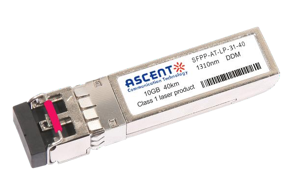
10G SFP+ LR 1310 nm 40 km
10 Gb/s 1310nm SFP+ 40 km Transceiver

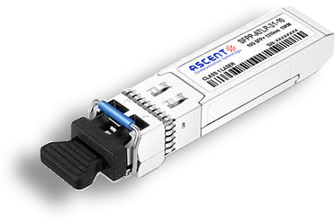
10G SFP+ LR 1310 nm 20 km
SFPP-ATLP-31-20 SFP+ Plug-in, 10Gbps, 20km, TX=1310/RX wide, on two single mode fibers, LC/PC Blue
10G SFP+ LR 1310 nm 10 km
SFPP-ATLP-31-10 SFP+ Plug-in, 10Gbps, 10km, TX=1310/RX wide, on two single mode fibers, LC/PC Blue

10G SFP+ LRM 1310 nm 2 km
SFPP-ATLP-31-02 10Gb/s 1310nm SFP+ 2 km Transceiver
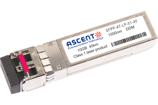
10G SFP+ ER 1550 nm 40 km
SFPP-ATLP-51-40 10 Gb/s 1550 nm SFP+ 40 km Transceiver
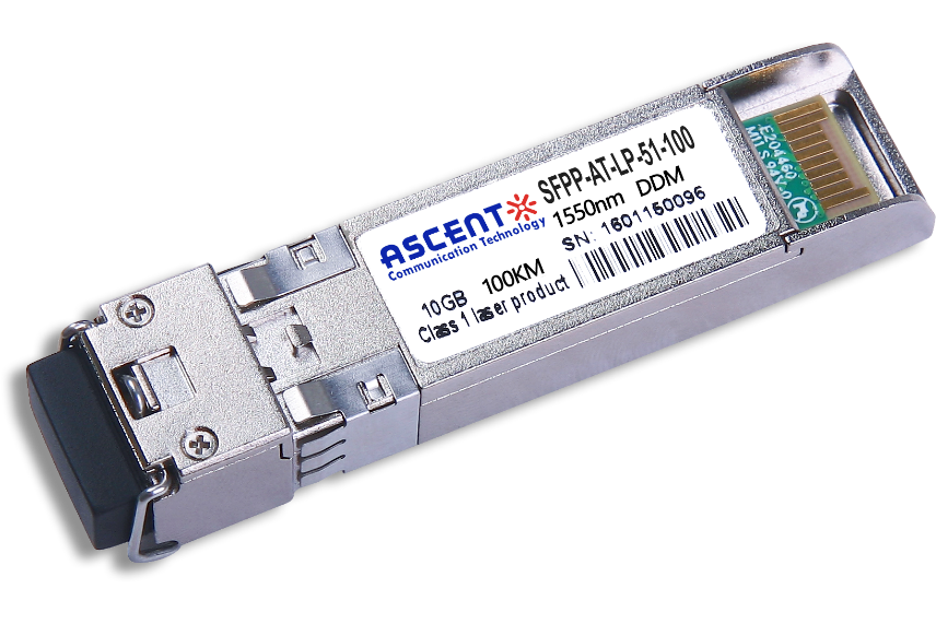
10G SFP+ CDR 1550 nm 100 km
SFPP-ATLP-51-100 10 Gb/s 1550 nm SFP+ 100 km Transceiver
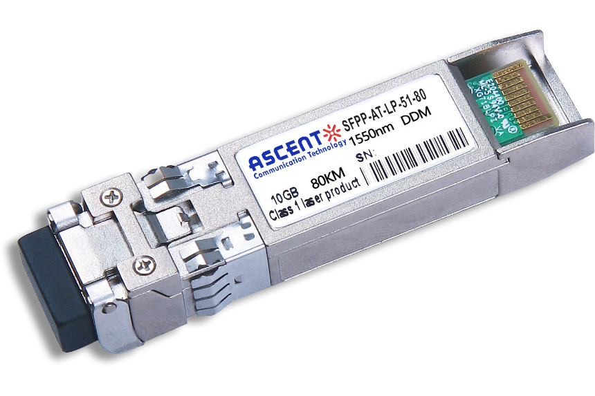
10G SFP+ ZR 1550 nm 80 km
SFPP-ATLP-51-80 10 Gb/s 1550 nm SFP+ 80 km Transceiver
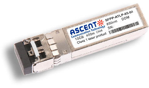
10G SFP+ 850 nm 400 m
10 Gb/s 850nm Multi-mode SFP+ Transceiver 400m
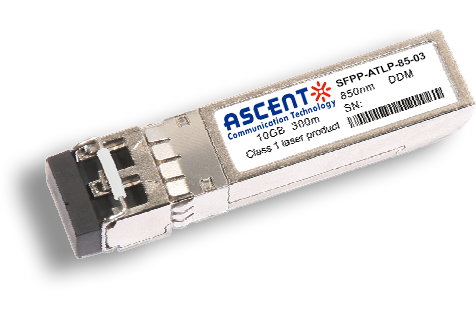
10G SFP+ 850 nm 300 m
SFPP-ATLP-85-03 10 Gb/s 850nm Multi-Mode SFP+ Transceiver
10G SFP+ Tunable DWDM 80 km
SFPP-LP-T99R-80 10 Gb/s Tunable DWDM SFP+ 80 km Transceiver
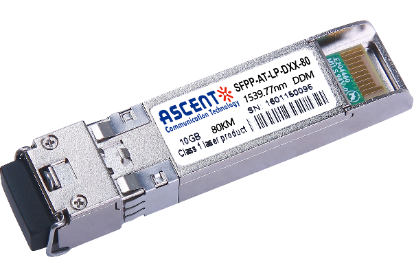
10G SFP+ DWDM 80 km
SFPP-ATLP-DXX-80 10 Gb/s DWDM SFP+ 80 km Transceiver
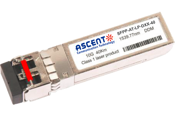
10G SFP+ DWDM 40 km
SFPP-ATLP-DXX-40 SFP+ Plug-in, 10Gbps, 40km, TX=ITU Ch xx (17 to 61) /RX wide, on two single mode fibers, LC/PC Blue
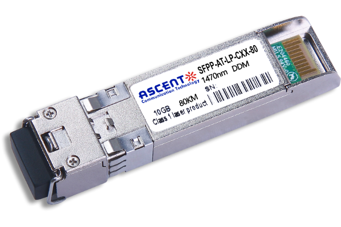
10G SFP+ CWDM 80 km
SFPP-ATLP-CXX-80 SFP+ Plug-in, 10 Gbps, 80 km, TX = CWDM Ch xx (1470ô nm to 1610 nm)/RX wide, on two single-mode fibers, LC/PC Blue.
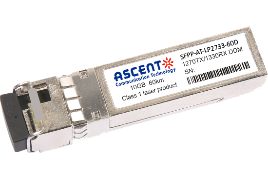
10G SFP+ CWDM 2733 60 km
SFPP-AT-LP-XXXX-60D 10 Gb/s BIDI SFP+ 60 km Transceiver
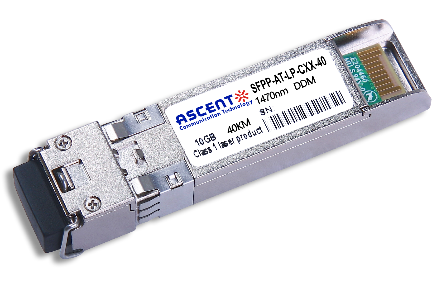
10G SFP+ CWDM 40 km
SFPP-ATLP-CXX-40 SFP+ Plug-in, 10Gbps, 40km, TX=CWDM Ch xx (1270ô nm to 1610 nm) /RX wide, on two single mode fibers, LC/PC Blue
10G SFP+ CWDM 10 km
10 Gb/s CWDM SFP+ 10 km Transceiver
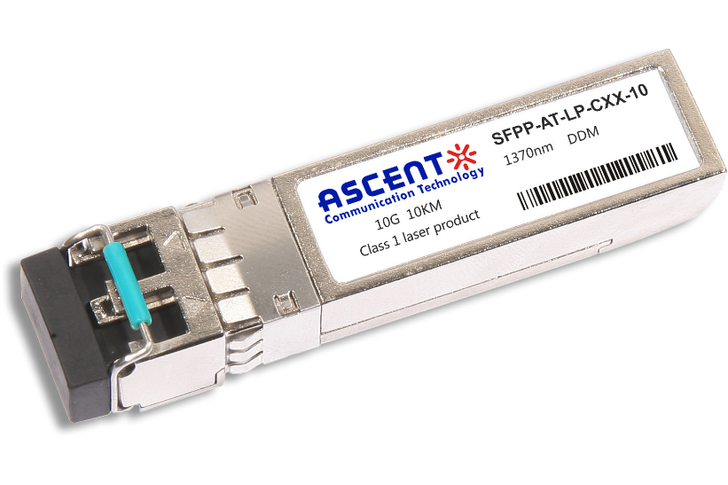
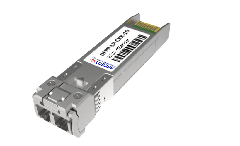
10G SFP+ Single mode CWDM 10 km
SFPP-ATLP-CXX-10 SFP+ Plug-in, 10 Gbps, 10 km, TX=CWDM Ch xx (1270 nm to 1610 nm)/RX wide, on two single-mode fibers, LC/PC Blue
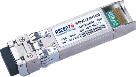
10G SFP+ CWDM 4955 80 km
SFP+ BIDI 10 Gb/s 1490/1550 nm 80 km Transceiver
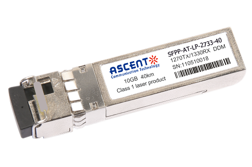
10G SFP+ CWDM 2733 40 km
SFPP-AT-LP-XXXX-40 SFP+ Plug-in, 10Gbps, 40km, TX=1270/RX=1330 , on one single mode fibers, LC/PC Blue
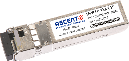
10G SFP+ CWDM 2733 10 km
SFPP-LP-XXXX-10 SFP+ Plug-in, 10Gbps, 10km, TX=1270/RX=1330 , on one single mode fibers, LC/PC Blue

10G XFP BIDI 80KM
XFP 10 Gb/s BIDI Single-Mode 80 km Transceiver DDM

10G XFP BIDI 40KM
XFP 10 Gb/s BIDI Single-Mode 40 km Transceiver DDM

10G XFP BIDI 20KM
XFP 10 Gb/s BIDI Single-Mode 20 km Transceiver DDM

10G XFP BIDI 10KM
XFP 10 Gb/s BIDI Single-Mode 10 km Transceiver DDM

10G XFP LR 1310 nm 20 km
XFP-AT-LP-31-20 10 Gb/s 20 km XFP Transceiver

10G XFP LR 1310 nm 10 km
XFP-AT-LP-31-10 10 Gb/s 10 km XFP Transceiver
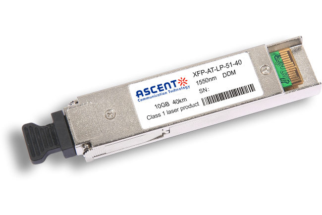
10G XFP ER 1550 nm 40 km
XFP-AT-LP-51-40 10 Gb/s 40 km XFP Optical Transceiver

10G XFP ZR 1550 nm 80 km
XFP-AT-LP-51-80 10 Gb/s 80 km XFP Optical Transceiver
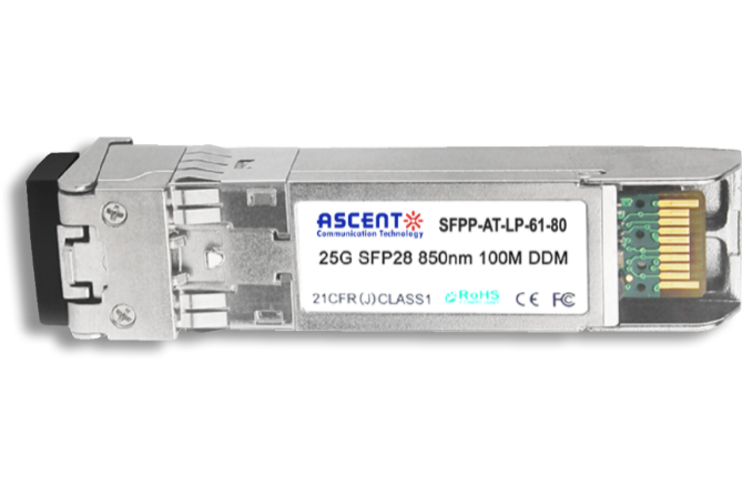
10G SFP+ CWDM 1610 80 km
SFPP-ATLP-61-80 SFP+ Plug-in, 10Gbps, 80km, TX=1610/RX wide, on two single mode fibers, LC/PC Blue
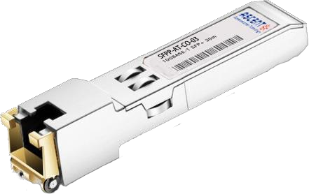
10G SFP+ Copper RJ45 30 m
SFPP-AT-CO-03 10GBASE-T SFP+ Copper RJ45 30m Transceiver

10G X2 850nm 300m
X2 10Gb/s 850nm Multi-mode Transceiver 300m
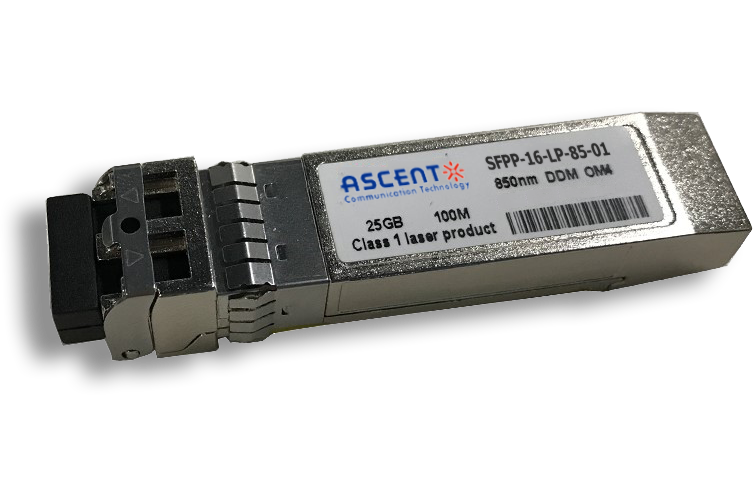
16G SFP+ FC 850 nm 100 m
SFPP-16-LP-85-01 16 Gb/s 850 nm SFP+ 100 m Transceiver
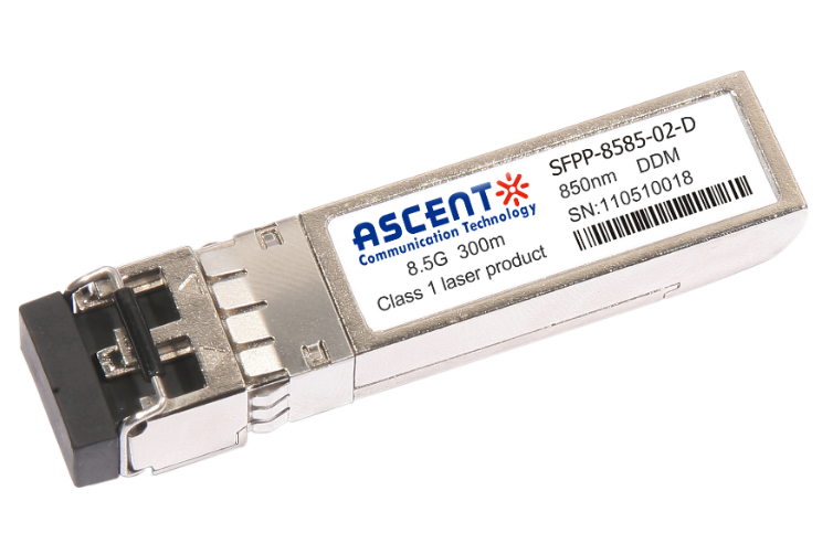
8.5G SFP+ SR 850 nm 150 m
SFPP-A8LP-85-015 8.5 Gb/s 850 nm Multi-Mode SFP+ Transceiver
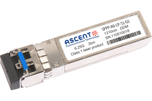
6.25G SFP+ LRM 1330 nm 2 km
SFPP-A6-LP-31-02 6.25 Gb/s Single-Mode SFP+ Transceiver
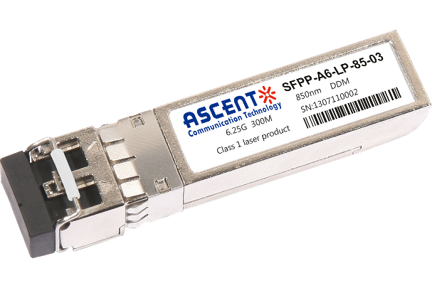
6.25G SFP+ SR 850 nm 300 m
SFPP-A6-LP-85-03 6.25 Gb/s 850 nm Multi-Mode SFP+ Transceiver
White Paper
Press Releases
Briefings 1
Briefings 2
Videos, etc.
QRG
Manual1
Manual2
Get in touch with our experts
Feedback