- FTTH ã 10G XGSPON >SFP Transceivers >1.25G SFP BX 3155 20 km

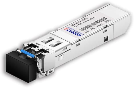
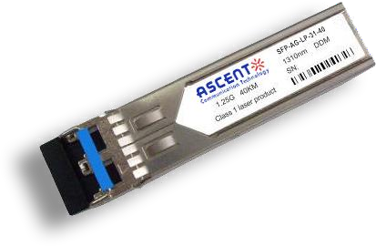
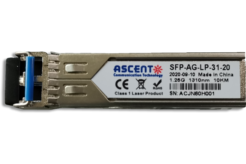
1.25G SFP BX 3155 20 km
Ascentãs SFP BIDI 1.25G 20 km transceiver is a compact and efficient optical interface designed for switches, routers, servers, and other networking equipment. Supporting data rates up to 1.25 Gb/s, the module fully complies with the SFP Multi-Source Agreement (MSA) and enables cost-effective bi-directional transmission over a single strand of single-mode fiber. The module offers flexible control through both a TTL-level TX Disable input and an IôýC-based digital management interface, allowing precise monitoring and protection of the optical transmitter. A TX Fault indicator provides early warning of potential laser degradation to help ensure long-term link stability. A dedicated Loss of Signal (LOS) output enhances system reliability by detecting insufficient receiver input or partner-device link issues. All key operational statesãLOS, link status, disable control, and fault conditionsãare accessible via the integrated digital diagnostic interface, supporting real-time system monitoring and remote management.
ôñ Up to 1.25Gb/s Data Links
ôñ A type:1310nm FP Tx/1550nm Rx
ôñ B type:1550nm DFB Tx/1310nm Rx
ôñ Hot-Pluggable SFP footprint
ôñ Single LC for Bi-directional Transmission
ôñ Built-in digital diagnostic functions
ôñ Up to 20km on 9/125ö¥m SMF
ôñ Single +3.3V Power Supply
ôñ Operating Temperature:
Standard: 0ô¯C to +70ô¯C
Industrial: -40ô¯C to +85ô¯C
ôñ Very low EMI and excellent ESD protection
ôñ RoHS compliant and Lead Free
Absolute Maximum Ratings
Parameter Operating Case Temperature | Symbol Top | Min. 0 | Typ.
| Max. +70 | Unit ô¯C | Note Commercial |
-40 | +85 | ô¯C | Industrial | |||
Power Supply Voltage | Vcct, R | -0.5 | 4 | V | ||
Relative Humidity | RH | 0 | 85 | % |
Optical Characteristics(TOP = Tc, VCC = 3.135 to 3.465 Volts)
Parameter | Symbol | Min. | Typ. | Max. | Unit | Note |
Transmitter | ||||||
Center Wavelength | ö£c | 1290 | 1310 | 1330 | nm | SFP-LP-3155-20 1 |
SFP-LP-3155-20A 1 | ||||||
ö£c | 1530 | 1550 | 1570 | nm | SFP-LP-5531-20 1 | |
SFP-LP-5531-20A 1 | ||||||
Spectral Width | ü | 3 | nm | |||
Optical Output Power | Pout | -9 | -3 | dBm | 2 | |
Optical Rise/Fall Time | tr / tf | 160 | ps | 3 | ||
Extinction Ratio | ER | 9 | dB | |||
Deterministic Jitter Contribution | TXöDJ | 56.5 | ps | 4 | ||
Total Jitter Contribution | TXöTJ | 119 | ps | 3 | ||
Eye Mask for Optical Output | Compliant with Eye Mask Defined in IEEE 802.3 standard | |||||
Relative Intensity Noise | RIN | -120 | dB/Hz | |||
Receiver | ||||||
Optical Input Wavelength | ö£c | 1530 | 1550 | 1570 | nm | SFP-LP-3155-20 |
SFP-LP-3155-20A | ||||||
ö£c | 1290 | 1310 | 1330 | nm | SFP-LP-5531-20 | |
SFP-LP-5531-20A | ||||||
Receiver Overload | Pol | -3 | dBm | 5.6 | ||
RX Sensitivity | Sen | -22 | dBm | 5.6 | ||
RX_LOS Assert | LOSA | -38 | dBm | |||
RX_LOS Deassert | LOSD | -23 | dBm | |||
RX_LOS Hysteresis | LOSH | 0.5 | dB | |||
General Characteristics | ||||||
Data Rate | ||||||
Data Rate | BR | 1.25 | Gbps | |||
Bit Error Rate | BER | 10-12 | ||||
Max. Supported Link Length on 9/125ö¥m SMF@1.25G | LMAX | 20 | km | 7 | ||
Total System Budget | LB | 14 | dB | 8 | ||
Notes:
1. The optical power is launched into SMF.
2. 20 to 80%.
3. Contributed total jitter is calculated from DJ and RJ measurements using TJ = RJ + DJ. Contributed RJ is calculated for 1x10-12 BER by multiplying the RMS jitter (measured on a single rise or fall edge) from the oscilloscope by 14. Per FC-PI, the actual contributed RJ is allowed to increase above its limit if the actual contributed DJ decreases below its limits, as long as the component output DJ and TJ remain within their specified FC-PI maximum limits with the worst case specified component jitter input.
4. Measured with PRBS 27-1 at 10-12 BER.
Electrical Characteristics (TOP = Tc, Vcc = 3.135 to 3.465 Volts)
Parameter | Symbol | Min. | Typ. | Max. | Unit | Notes |
Supply Voltage | Vcc | 3.14 | 3.30 | 3.47 | V | |
Supply Current | Icc | 300 | mA | |||
Inrush Current | Isurge | Icc+30 | mA | |||
Maximum Power | Pmax | 1.0 | mW | |||
Transmitter | ||||||
Input Differential Impedance | Rin | 90 | 100 | 110 | ||
Single Ended Data Input Swing | Vin,PP | 200 | 1200 | mVp-p | ||
Transmit Disable Voltage | VD | Vcc - 1.3 | Vcc | V | 2 | |
Transmit Enable Voltage | VEN | Vee | Vee+ 0.8 | V | ||
Transmit Disable Assert Time | Tdessert | 10 | us | |||
Receiver | ||||||
Single Ended Data Output Swing | Vout,pp | 300 | 80 | mv | 3 | |
Data Output Rise Time | tr | 150 | ps | 4 | ||
Data Output Fall Time | tf | 150 | ps | 4 | ||
LOS Fault | Vlosfault | Vcc ã 0.5 | VCC_host | V | 5 | |
LOS Fault | Vlos norm | Vee | Vee+0.5 | V | 5 | |
Power Supply Rejection | PSR | 100 | 0.5 | mVpp | 6 | |
Deterministic Jitter Contribution | RXöDJ | 51.7 | ps | 7 | ||
Total Jitter Contribution | RXöTJ | 122.4 | ps | |||
Notes:
1. AC coupled.
2. Or open circuit.
3. Into 100 ohm differential termination.
4. LOS is LVTTL. Logic 0 indicates normal operation; logic 1 indicates no signal detected.
5. All transceiver specifications are compliant with a power supply sinusoidal modulation of 20Hz to 1.5MHz up to specified value applied through the power supply filtering network shown on page23 of the Small Form-factor Pluggable (SFP) Transceiver Multi-Source Agreement (MSA), September 14, 2000.
6. Measured with DJ-free data input signal. In actual application, output DJ will be the sum of input DJ and . DJ.


2.5G SFP 1550nm 80km
SFP 1550nm 2.5Gbps 80km Transceiver
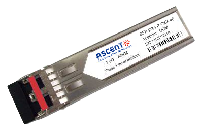
2.5G SFP CWDM 40 km
SFP-2G-LP-CXX-40 2.5 Gbps CWDM Single-mode SFP Transceiver
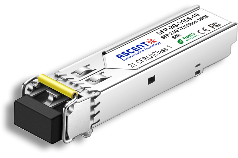
2.5G SFP BiDi 10 km
SFP-2G-LP-3155-10 2.5 Gb/s BiDi Single-mode SFP Transceiver

2.5G SFP 1310nm 20km
SFP 1310nm 2.5Gbps LX 20km Transceiver
2.5G SFP 1310nm 10km
2.5 Gb/s 1310nm Single-mode SFP Transceiver
2.5G SFP 1310 nm 2 km
SFP-2G-LP-31-2K 2.5 Gb/s 1310 nm Single-mode SFP Transceiver
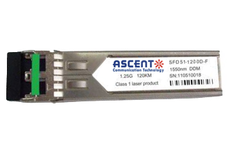
1.25G SFP EZX 1550 nm 120 km
SFP-AGLP-51-120 1.25Gb/s 1550nm Single-mode SFP Transceiver
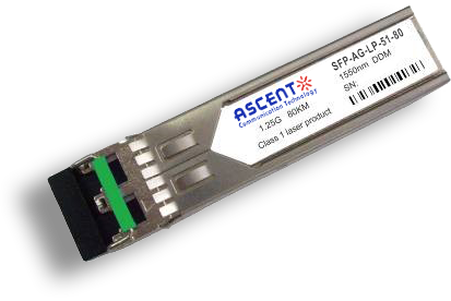
1.25G SFP ZX 1550 nm 80 km
SFP-AG-LP-51-80 1.25 Gb/s 1550 nm Single-Mode SFP Transceiver
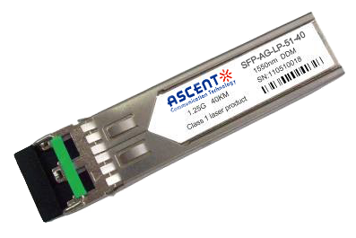
1.25G SFP EX 1550 nm 40 km
SFP-AG-LP-51-40 1.25 Gbps 1550 nm Single-mode SFP Transceiver
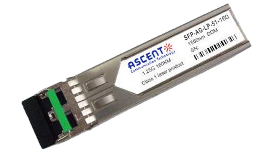
1.25G SFP 1550 nm 160 km
1.25 Gb/s SFP 1550nm 160km Transceiver
1.25G SFP EX 1310 nm 40 km
SFP-AG-LP-31-40 1.25 Gb/s 1310 nm Single-mode SFP Transceiver
1.25G SFP 1310 nm 20 km
SFPP-AG-LP-31-20 1.25 Gb/s 1310 nm Single-Mode SFP Transceiver

1.25G SFP 1310 nm 10 km
SFPP-AG-LP-31-10 1.25 Gb/s 1310 nm Single-Mode SFP Transceiver

1.25G SFP SR 850 nm 550 m
SFP-AG-LP-85-05 1.25Gb/s 850 nm Multi-Mode SFP Transceiver
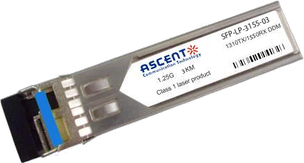
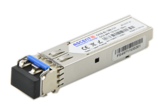
1.25G SFP BX 3155 3 km
SFP BIDI 1.25G 1310/1550 nm 3 km
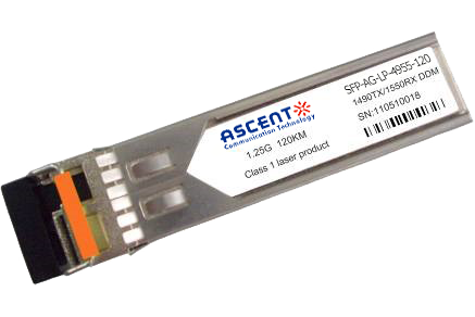
1.25G SFP BX 4950 120 km
SFP-AGLP4955-120 SFP BIDI 1.25G 1490/1550 nm 120 km DDM

1.25G SFP BX 4950 80 km
SFP-AGLP-4955-80 SFP BIDI 1.25G 1490/1550 nm 80 km DDM

1.25G SFP BX 3150 40 km
SFP-AGLP-3155-40 SFP BIDI 1.25G 1310/1550 nm 40 km DDM
1.25G SFP BX 3149 20 km
SFP-AGLP-3149-20 SFP BIDI 1.25G 1310/1490 nm 20 km DDM
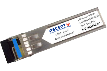
1.25G SFP CWDM 4931 20 km
SFP-AGSP-4931-20 SFP Plug-in, 1.25Gbps, 20km, BIDI, TX=1490nm, RX=1310nm, SC/PC Blue

1000M Copper SFP
SFP-AG-CO-01 1000M Copper SFP Transceiver
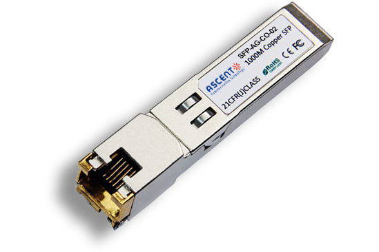
10/100/1000M Copper SFP
SFP-AG-CO-02 10/100/1000M Copper SFP Transceiver

1000M Copper SFP w/ Auto-Negotiation
SFP-AG-CO-03 1000M Auto Adapt Copper SFP Transceiver
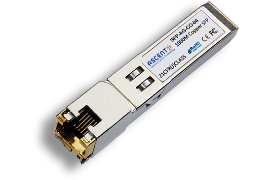
10/100/1000M Copper SFP w/ Link Indicator
SFP-AG-CO-04 10/100/1000M Copper SFP Transceiver w/ Link Indicator
155M SFP 1550 nm 80 km
SFP-AF-LP-51-80 155 Mb/s 1550ô nm Single?Mode SFP Transceiver

155M SFP OC3 1310nm 15 km
SFP_ONS-SI-155-I1 SFP Plug-in, OC3 155Mbps 1310nm Single-mode SFP Optical Transceiver, 15km, LC
White Paper
Press Releases
Briefings 1
Briefings 2
Videos, etc.
QRG
Manual1
Manual2
Get in touch with our experts
Feedback