- HFC CABLE TV >RF Amplifiers >ARF120D RF AMP

ARF120D RF AMP
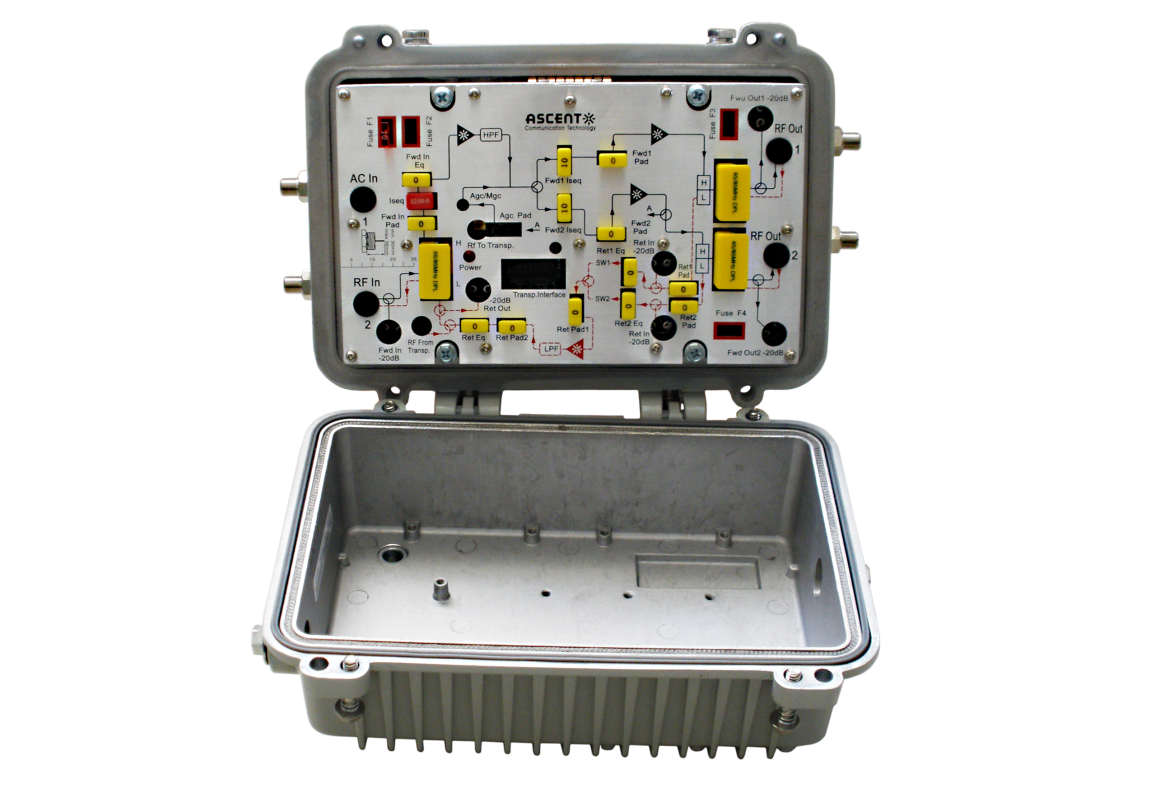
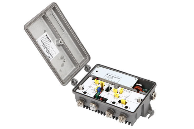
ARF120D Series 1.2 GHz 1 or 2 output GaAs amplifier is part of ACT Advanced Fiber Deep HFC solution, which has been designed to deliver interactive CATV, high capacity DOCSIS and other advanced services. The cost effective last mile amplifier platform helps operators expand bandwidth of their existing HFC network while minimizing capital investment. The ARF120D compact housing has compact housing with embedded RF module and is suitable for MDU, FTTB or FTTC applications with output up to 108ô dBôçV.
ã Supports 1.2 GHz bandwidth
ã Up to 204 MHz with return bandwidth
ã Minimum needed of installing and maintaining accessories such as pads and EQs
ã Local monitoring, control and set up via APP or 3-bit digital tube display and adjust keypad
ã On-site changing frequency split
ã Reverse path gain adjust switching and passive
ã Compact design
ã GaAs technology
ã Improved ESD and surge protection
ã Low noise figure
ã One or two output can be determined by the splitter position
Item | Description |
Pass Band | 85/105/258 MHz to 1218 MHz |
Gain1 | 42 dB |
Frequency Response | ôÝ0.75 dB |
Reference Output Level | 108 dBôçV |
Input Attenuator Control Range | 0 dB to 20 dB, 1 dB step |
Input Equalizer Control Range | 0 dB to 20 dB, 1 dB step |
Input Cable Simulator | 0 dB to 10 dB, 1 dB step, adjust via JXP PAD |
Interstage Attenuator Control Range | 0 dB to 20 dB, 1 dB step |
Interstage Equalizer Control Range | 0 dB to 20 dB, 1 dB step |
Return Loss | 16 dB |
RF Input Test Point | ã20 dB ôÝ 0.75 dB |
RF Output Test Point | ã20 dB ôÝ 0.75 dB |
Noise Figure1 | 7 dB |
Umax, 112 QAM Chs2 | 108 dBôçV |
Output Level, CENELEC 42 Chs3 CTB3: 60 dBc3 CSO3: 60 dBc3 | 112 dBôçV |
Notes:
1. Forward Gain and Noise Figure measured with 10 dB input EQ and 0 dB input pad.
2. Maxima level, flat, CLC/TS 50083ã3ã3, N=24.
3. Distortion performance reference output level is 112 dBôçV (1 port, Slope, 10dB @ 1200 MHz). Digital refers to 550 MHz to 1.2 GHz loading with QAM carriers at ã6 dB relative to analog CW carrier levels.
Return Path Specifications
Item | Description |
Pass Band | 5 MHz to 65/85/204 MHz |
Gain | 25 dB |
Output Attenuator Control Range | 0 dB to 20 dB, 1 dB step |
Output Equalizer Control Range | 0 dB to 20 dB, 1 dB step |
Frequency Response | ôÝ0.75 dB |
Return Loss | 16 dB |
RF Test Point | ã20 dB ôÝ 0.1 dB |
Noise Figure | 6 dB |
Output Level | 110 dBôçV |
General Specifications
Item | Description |
Power Consumption | 18 W |
Supply Voltage | 26 VAC to 65 VAC or 110 VAC to 264 VAC |
RF Connectors | Fãfemale, Imperial (Several Adapters Available) |
Test Point | Fãfemale, Imperial (Internal) |
Dimensions (WûHûD) | 236 mm û 145 mm û 90 mm |
Weight | 1.8 kg |
Water/Dust Ingress Protection Rating | IP65 |
Operating Temperature | ã40 ô¯C to +55 ô¯C |
Storage Temperature | ã40 ô¯C to + 80 ô¯C |
Relative Humidity Range | 5 % to 95 % |
Note: Unless otherwise noted, all specifications reflect typical performance and are referenced to 20 ô¯C.

ARF230 RF AMP
ARF230 High-Output Two-Way Trunk/Line Amplifier

ARF130C Trunk AMP
MDU 1 or 2 O/P Trunk Amplifier
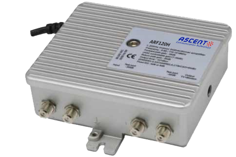
ARF120H RF AMP
1.2 GHz RF Amplifier
ARF120G MDU AMP
1.2 GHz MDU Amplifier
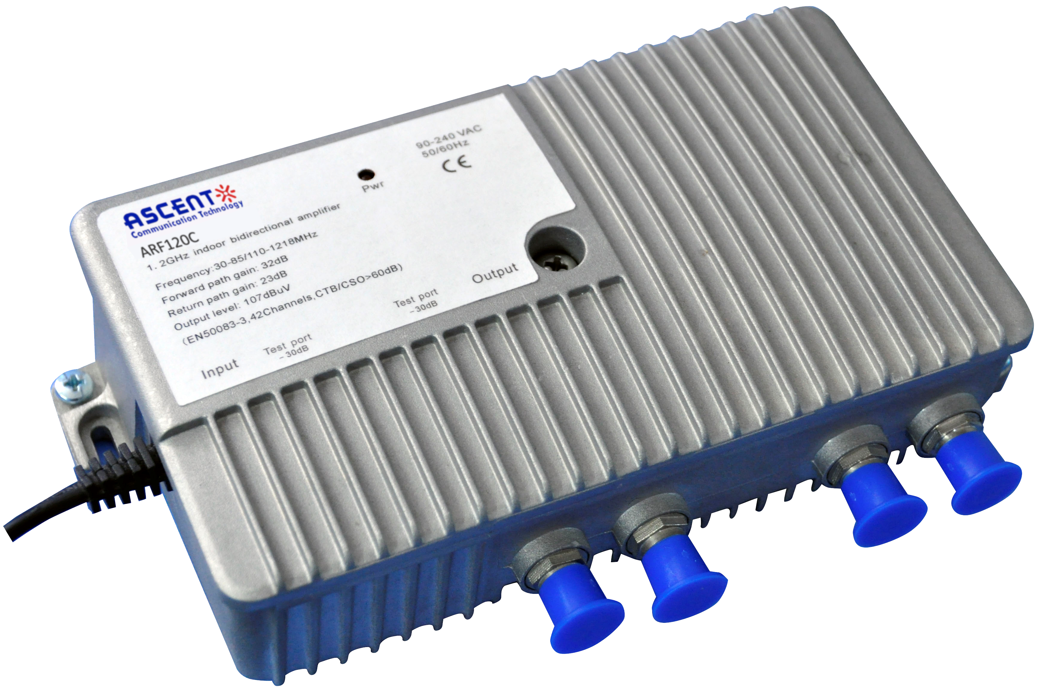
ARF120C MDU AMP
1.2GHz MDU Amplifier Deep Fiber Solution
ARF120 RF AMP
ARF120B 1.2 GHz GaAs MDU Amplifier

ARF110C Trunk AMP
MDU 1 or 2 -port Line Amplifier
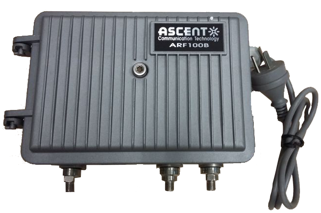
ARF100B LE AMP
ARF100B 1 or 2 RF Outputs MDU Amplifier
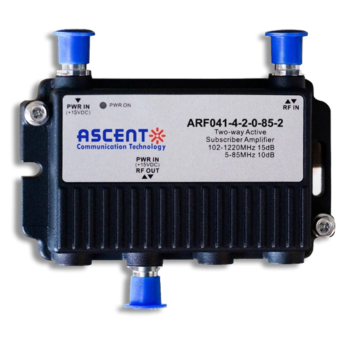
ARF040 RF AMP
Bi-Directional House Amplifier
White Paper
Press Releases
Briefings 1
Briefings 2
Videos, etc.
QRG
Manual1
Manual2
Get in touch with our experts
Feedback