- FTTH ã 10G XGSPON >SFP Transceivers >100M SFP BX 4931 20 km
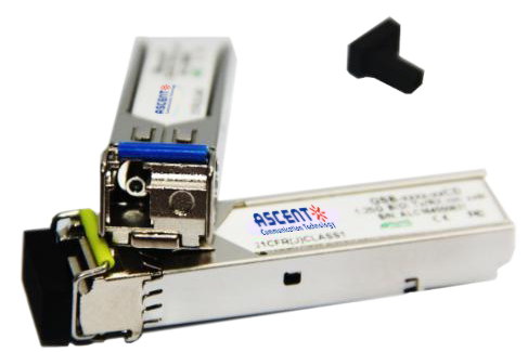
100M SFP BX 4931 20 km
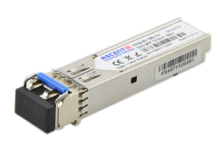
Ascentãs SFPP-AF-LP-XXXX-20-AN transceivers are designed expressly for high-speed communication applications that require rates up to 155 Mb/s. They are designed to be compliant with the SFF-8472 SFP MSA. The module is suitable for data links up to 20 km in distance over a 9/125 ôçm single mode fiber.
ã Up to 155 Mbps Data Links
ã Up to 20 km transmission on SMF
ã 1310 nm FP laser and PIN receiver for SFP-AF-LP-5531-20-AN
ã 1550 nm FP laser and PIN receiver for SFP-AF-LP-3155-20-AN
ã Compliant with SFP+ MSA with LC connector
ã Compliant with SFF 8472
ã +3.3 V single power supply
Absolute Maximum Ratings
Parameter | Symbol | Min | Max | Unit |
Supply Voltage | Vcc | ã0.5 | 4.5 | V |
Storage Temperature | Ts | ã40 | +85 | ô¯C |
Operating Humidity | ã | 5 | 85 | % |
Recommended Operating Conditions
Parameter | Symbol | Min | Typical | Max | Unit | |
Operating Case Temperature | Standard | Tc | 0 | +70 | ô¯C | |
Industrial | ã40 | +85 | ô¯C | |||
Power Supply Voltage | Vcc | 3.13 | 3.3 | 3.47 | V | |
Power Supply Current | Icc | 300 | mA | |||
Data Rate | 155 | Mbps | ||||
Optical and Electrical Characteristics (SFPãAFãLPã5531ã20ãAN)
Parameter | Symbol | Min | Typical | Max | Unit | Notes | |
Transmitter | |||||||
Centre Wavelength | ö£c | 1500 | 1550 | 1600 | nm | ||
Spectral Width (ã20dB) | ãö£ | 4 | nm | ||||
Average Output Power | Pout | ã14 | ã8 | dBm | 1 | ||
Extinction Ratio | ER | 9 | dB | ||||
Data Input Swing Differential | VIN | 400 | 1800 | mV | 2 | ||
Input Differential Impedance | ZIN | 90 | 100 | 110 | öˋ | ||
TX Disable | Disable | 2.0 | Vcc | V | |||
Enable | 0 | 0.8 | V | ||||
TX Fault | Fault | 2.0 | Vcc | V | |||
Normal | 0 | 0.8 | V | ||||
Receiver | |||||||
Centre Wavelength | ö£c | 1260 | 1360 | nm | |||
Receiver Sensitivity | ã32 | dBm | 3 | ||||
Receiver Overload | ã3 | dBm | 3 | ||||
LOS DeãAssert | LOSD | ã32 | dBm | ||||
LOS Assert | LOSA | ã45 | dBm | ||||
LOS Hysteresis | 1 | 4 | dB | ||||
Data Output Swing Differential | Vout | 400 | 1800 | mV | 4 | ||
LOS | High | 2.0 | Vcc | V | |||
Low | 0.8 | V | |||||
Notes:
1. The optical power is launched into SMF.
2. PECL input, internally ACãcoupled and terminated.
3. Measured with a PRBS 223ã1 test pattern @155Mbps, BER ãÊ1û10ã10.
4. Internally ACãcoupled.
Optical and Electrical Characteristics (SFPãAFãLPã3155ã20ãAN)
Parameter | Symbol | Min | Typical | Max | Unit | Notes | ||
Transmitter | ||||||||
Centre Wavelength | ö£c | 1260 | 1310 | 1360 | nm | |||
Spectral Width (RMS) | ãö£ | 4 | nm | |||||
Average Output Power | Pout | ã15 | ã7 | dBm | 1 | |||
Extinction Ratio | ER | 9 | dB | |||||
Data Input Swing Differential | VIN | 400 | 1800 | mV | 2 | |||
Input Differential Impedance | ZIN | 90 | 100 | 110 | öˋ | |||
TX Disable | Disable | 2.0 | Vcc | V | ||||
Enable | 0 | 0.8 | V | |||||
TX Fault | Fault | 2.0 | Vcc | V | ||||
Normal | 0 | 0.8 | V | |||||
Receiver | ||||||||
Centre Wavelength | ö£c | 1480 | 1580 | nm | ||||
Receiver Sensitivity | ã28 | dBm | 3 | |||||
Receiver Overload | ã3 | dBm | 3 | |||||
LOS DeãAssert | LOSD | ã29 | dBm | |||||
LOS Assert | LOSA | ã45 | dBm | |||||
LOS Hysteresis | 0.5 | 2 | 6 | dB | ||||
Data Output Swing Differential | Vout | 400 | 1800 | mV | 4 | |||
LOS | High | 2.0 | Vcc | V | ||||
Low | 0.8 | V | ||||||
Notes:
1. The optical power is launched into SMF.
2. PECL input, internally ACãcoupled and terminated.
3. Measured with a PRBS 223ã1 test pattern @155Mbps, BER ãÊ1û10ã10.
4. Internally ACãcoupled.
Timing and Electrical
Parameter | Symbol | Min | Typical | Max | Unit |
Tx Disable Negate Time | t_on | 1 | ms | ||
Tx Disable Assert Time | t_off | 10 | ôçs | ||
Time To Initialize, including Reset of Tx Fault | t_init | 300 | ms | ||
Tx Fault Assert Time | t_fault | 100 | ôçs | ||
Tx Disable To Reset | t_reset | 10 | ôçs | ||
LOS Assert Time | t_loss_on | 100 | ôçs | ||
LOS Deãassert Time | t_loss_off | 100 | ôçs | ||
Serial ID Clock Rate | f_serial_clock | 400 | KHz | ||
MOD_DEF (0: 2)ãHigh | VH | 2 | Vcc | V | |
MOD_DEF (0: 2)ãLow | VL | 0.8 | V |
Diagnostics
Parameter | Range | Unit | Accuracy | Calibration |
Temperature | 0 to +70 (standard) | ô¯C | ôÝ3ô¯C | Internal / External |
ã40 to +85 (industrial) | ||||
Voltage | 3.0 to 3.6 | V | ôÝ3% | Internal / External |
Bias Current | 0 to 100 | mA | ôÝ10% | Internal / External |
TX Power | ã14 to ã8 | dBm | ôÝ3dB | Internal / External |
RX Power | ã30 to ã8 | dBm | ôÝ3dB | Internal / External |


2.5G SFP 1550nm 80km
SFP 1550nm 2.5Gbps 80km Transceiver
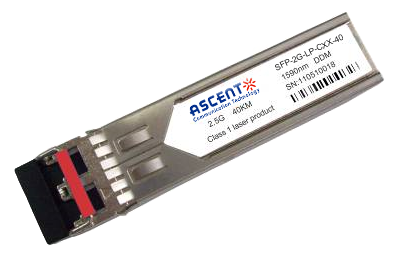
2.5G SFP CWDM 40 km
SFP-2G-LP-CXX-40 2.5 Gbps CWDM Single-mode SFP Transceiver
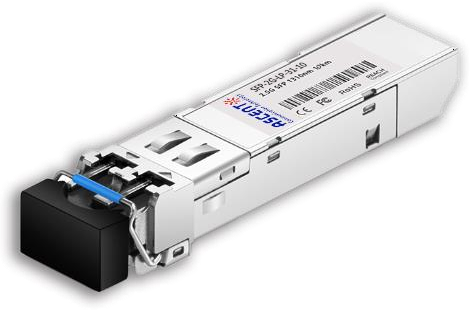
2.5G SFP BiDi 10 km
SFP-2G-LP-3155-10 2.5 Gb/s BiDi Single-mode SFP Transceiver

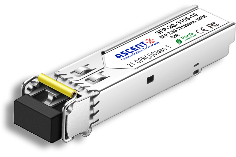
2.5G SFP 1310nm 20km
SFP 1310nm 2.5Gbps LX 20km Transceiver
2.5G SFP 1310nm 10km
2.5 Gb/s 1310nm Single-mode SFP Transceiver
2.5G SFP 1310 nm 2 km
SFP-2G-LP-31-2K 2.5 Gb/s 1310 nm Single-mode SFP Transceiver
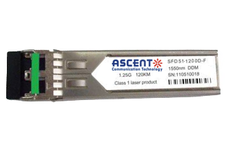
1.25G SFP EZX 1550 nm 120 km
SFP-AGLP-51-120 1.25Gb/s 1550nm Single-mode SFP Transceiver
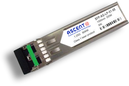
1.25G SFP ZX 1550 nm 80 km
SFP-AG-LP-51-80 1.25 Gb/s 1550 nm Single-Mode SFP Transceiver
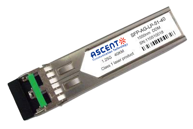
1.25G SFP EX 1550 nm 40 km
SFP-AG-LP-51-40 1.25 Gbps 1550 nm Single-mode SFP Transceiver
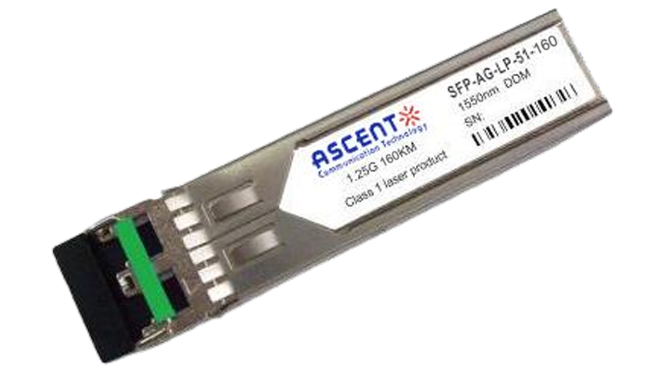
1.25G SFP 1550 nm 160 km
1.25 Gb/s SFP 1550nm 160km Transceiver
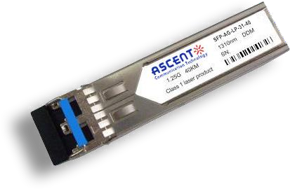
1.25G SFP EX 1310 nm 40 km
SFP-AG-LP-31-40 1.25 Gb/s 1310 nm Single-mode SFP Transceiver
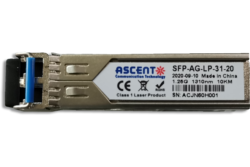
1.25G SFP 1310 nm 20 km
SFPP-AG-LP-31-20 1.25 Gb/s 1310 nm Single-Mode SFP Transceiver

1.25G SFP 1310 nm 10 km
SFPP-AG-LP-31-10 1.25 Gb/s 1310 nm Single-Mode SFP Transceiver

1.25G SFP SR 850 nm 550 m
SFP-AG-LP-85-05 1.25Gb/s 850 nm Multi-Mode SFP Transceiver

1.25G SFP BX 3155 20 km
SFP BIDI 1.25G 1310/1550 nm 20 km DDM
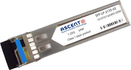
1.25G SFP BX 3155 3 km
SFP BIDI 1.25G 1310/1550 nm 3 km
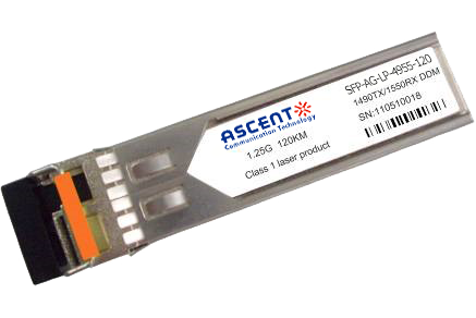
1.25G SFP BX 4950 120 km
SFP-AGLP4955-120 SFP BIDI 1.25G 1490/1550 nm 120 km DDM

1.25G SFP BX 4950 80 km
SFP-AGLP-4955-80 SFP BIDI 1.25G 1490/1550 nm 80 km DDM

1.25G SFP BX 3150 40 km
SFP-AGLP-3155-40 SFP BIDI 1.25G 1310/1550 nm 40 km DDM
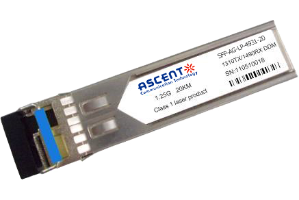
1.25G SFP BX 3149 20 km
SFP-AGLP-3149-20 SFP BIDI 1.25G 1310/1490 nm 20 km DDM
1.25G SFP CWDM 4931 20 km
SFP-AGSP-4931-20 SFP Plug-in, 1.25Gbps, 20km, BIDI, TX=1490nm, RX=1310nm, SC/PC Blue

1000M Copper SFP
SFP-AG-CO-01 1000M Copper SFP Transceiver
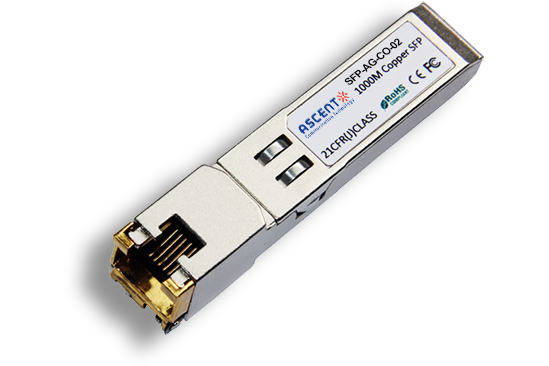
10/100/1000M Copper SFP
SFP-AG-CO-02 10/100/1000M Copper SFP Transceiver

1000M Copper SFP w/ Auto-Negotiation
SFP-AG-CO-03 1000M Auto Adapt Copper SFP Transceiver
10/100/1000M Copper SFP w/ Link Indicator
SFP-AG-CO-04 10/100/1000M Copper SFP Transceiver w/ Link Indicator
155M SFP 1550 nm 80 km
SFP-AF-LP-51-80 155 Mb/s 1550ô nm Single?Mode SFP Transceiver

155M SFP OC3 1310nm 15 km
SFP_ONS-SI-155-I1 SFP Plug-in, OC3 155Mbps 1310nm Single-mode SFP Optical Transceiver, 15km, LC
White Paper
Press Releases
Briefings 1
Briefings 2
Videos, etc.
QRG
Manual1
Manual2
Get in touch with our experts
Feedback