- FIBER OPTIC TRANSCEIVERS >Optical Cables and Accessories >200G QSFP56 to 2x100G QSFP56 DAC

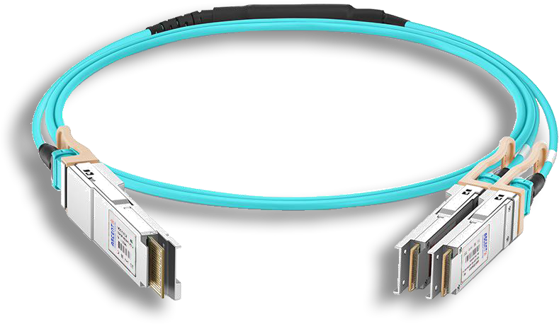
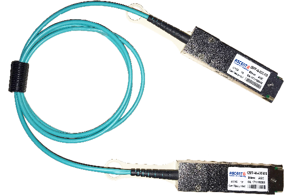
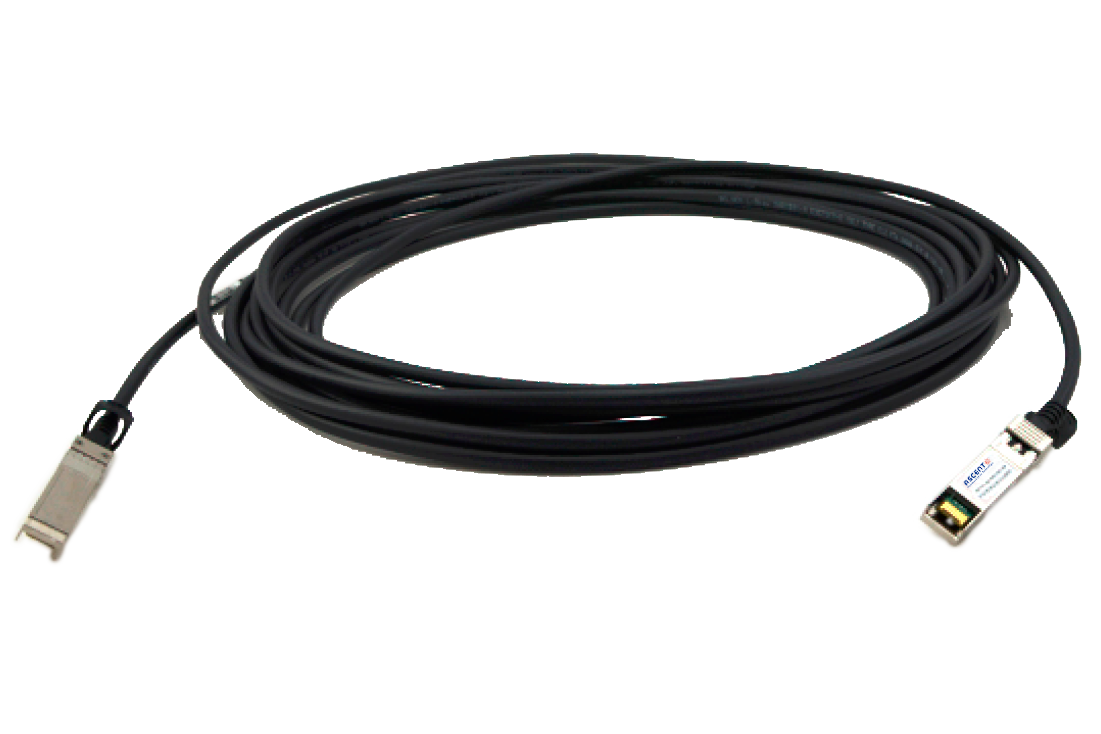
200G QSFP56 to 2x100G QSFP56 DAC
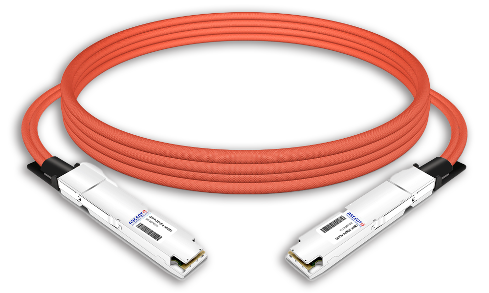
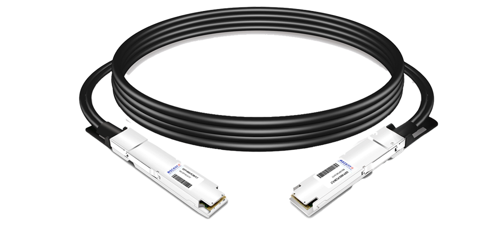
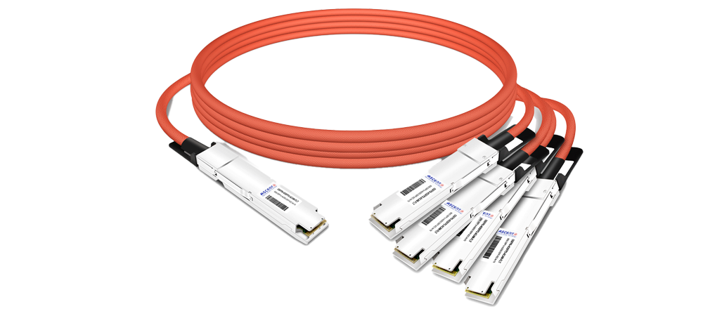
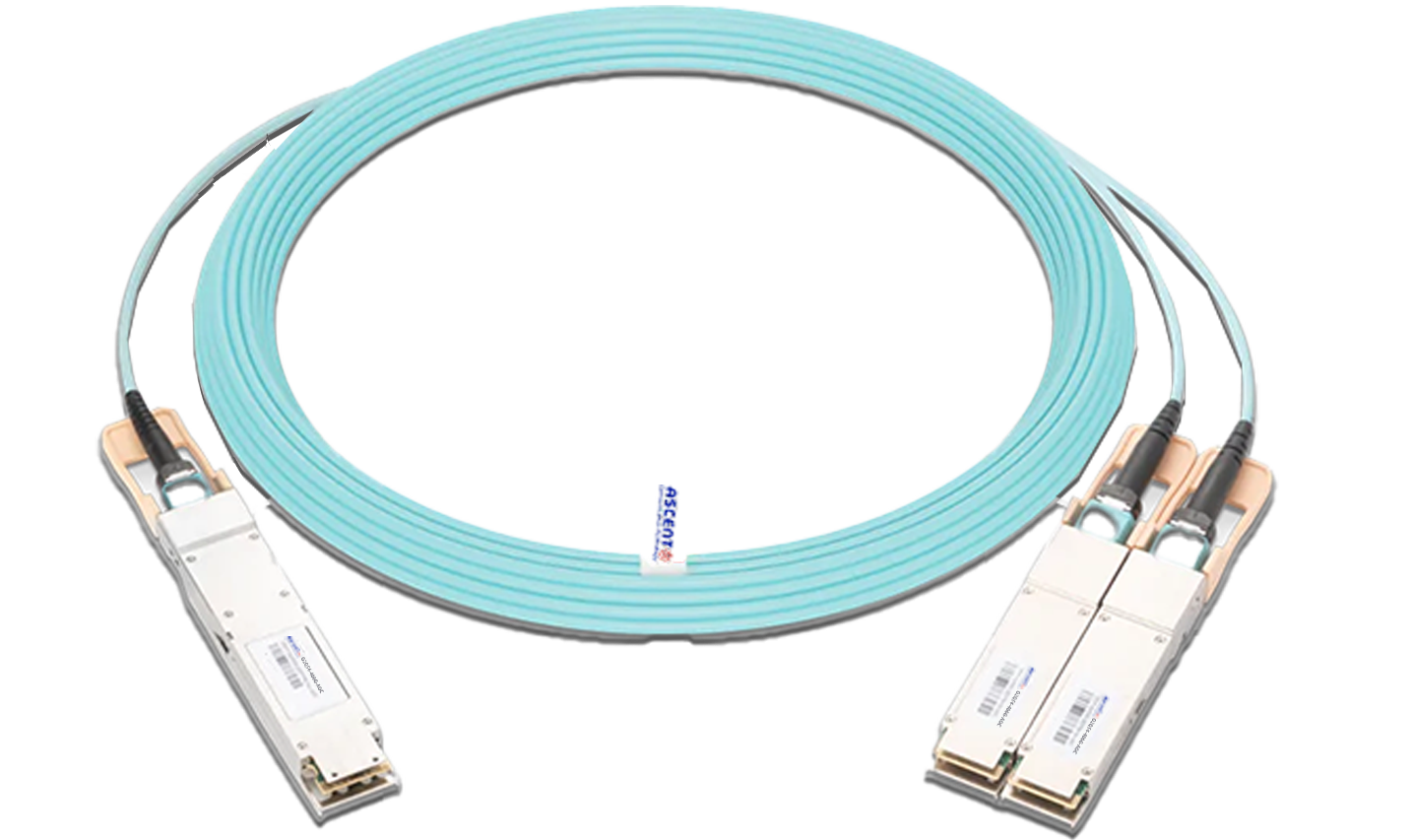
The 200G QSFP56 to 2x100G QSFP56 Direct Attach Copper Cable assembly features eight differential copper pairs, delivering four data transmission channels at speeds of up to 56 Gbps (PAM4) per channel. It meets the requirements for 200G Ethernet and InfiniBand High Data Rate (HDR) applications. This 200G cable assembly supports various wire gauges ranging from 26AWG to 30AWG and offers low insertion loss and minimal crosstalk. By utilizing PAM4 signaling, QSFP56 effectively doubles data transmission rates, though it demands stricter cable insertion loss specifications. For more information, please refer to the High-Speed Characteristics guidelines. Designed for high-speed and reliable connections in data centers, networking, and telecommunications, this next-generation product maintains compatibility with the QSFP+ form factor, ensuring backward compatibility with existing QSFP ports.
ôñ Compatible with IEEE 802.3bj and IEEE 802.3cd
ôñ In accordance with the paging function in the protocol SFF-8636, paging can be selected 00H or 02H in
127 bytes (page02 only supported by MCU type cable)
ôñ Supports aggregate data rates of 200Gbps(PAM4)
ôñ Optimized construction to minimize insertion loss and cross talk
ôñ Backward compatible with existing QSFP+ connectors and cages
ôñ Pull-to-release slide latch design
ôñ 26AWG through 30AWG cable
ôñ Straight and break out assembly configurations available
ôñ Customized cable braid termination limits EMI radiation
ôñ Customizable EEPROM mapping for cable signature
ôñ Operating temperature: 0ô¯C to 70ô¯C
ôñ Single 3.3V power supply
ôñ RoHS Compatible
High Speed Characteristics
Parameter | Symbol | Min | Typ. | Max | Unit | Note |
Differential Impedance | TDR | 90 | 100 | 110 | öˋ | |
Insertion Loss | SDD21 | -17.16 | dB | At 13.28 GHz | ||
Differential Return Loss
| SDD11
| See 1 | dB | At 0.05 to 4.1 GHz | ||
SDD22
| See 2 | dB | At 4.1 to 19 GHz | |||
Common-Mode to Common-Mode Output Return Loss | SCC11 SCC22
| -2 | dB | At 0.2 to 19 GHz | ||
Differential to Common-Mode return loss
| SCD11
| See 3 | dB | At 0.01 to 12.89 GHz | ||
SCD22
| See 4 | dB | At 12.89 to 19 GHz | |||
Differential to Common Mode Conversion Loss
| SCD21-IL | -10 | dB | At 0.01 to 12.89 GHz | ||
SCD21-IL | See 5 | dB | At 12.89 to 15.7 GHz | |||
SCD21-IL | -6.3 | dB | At 15.7 to 19 GHz |
Notes:
1. Reflection Coefficient given by equation SDD11(dB) < -16.5 + 2 û SQRT(f ), with f in GHz
2. Reflection Coefficient given by equation SDD11(dB) < -10.66 + 14 û log10(f/5.5), with f in GHz
3. Reflection Coefficient given by equation SCD11(dB) < -22 + (20/25.78)*f, with f in GHz
4. Reflection Coefficient given by equation SCD11(dB) < -15 + (6/25.78)*f, with f in GHz
5. Reflection Coefficient given by equation SCD21(dB) < -27 + (29/22)*f, with f in GHz
Regulatory Compliance
Feature | Reference | Performance |
Electrostatic Discharge (ESD) to the Electrical Pins | MIL-STD-883C Method 3015.7 | Class 1(>2000 Volts) |
Electromagnetic Interference (EMI) | FCC Class B | Compatible with standards |
CENELEC EN55022 Class B | ||
CISPR22 ITE Class B | ||
RF Immunity(RFI) | IEC61000-4-3 | Typically Show no Measurable from |
Effect from a 10V/m Field Swept | ||
80 to 1000MHz | ||
RoHS Compliance | RoHS Directive 2011/65/EU and it's Amendment Directives ÿ¥EUÿ¥ 2015/863 | RoHS ÿ¥EUÿ¥2015/863 compliant |
REACH Compliance | REACH Regulation (EC) No 1907/2006 | REACH (EC) No 1907/2006 compliant |

OSFP 800G ACC Cable
800G Twin-port 2x400G OSFP Active Copper Cable
OSFP 800G DAC Cable
800G Twin-port 2x400G OSFP Passive DAC Cable
800G OSFP to 4x200G Breakout ACC
800G 4x200G OSFP Breakout Active Copper Cable

400G OSFP to 400G QSFP-DD DAC
400G OSFP to 400G QSFP-DD Passive DAC Twinax Cable

400G OSFP to 4x100G QSFP56 DAC
400G OSFP to 4x100G QSFP56 Passive DAC Breakout Cable

400G QSFP DD DAC Cable
400G QSFP-DD Passive Direct Attach Copper Cable

400G QSFP DD to 4X100G QSFP56 AOC
400G QSFP-DD to 4x100G QSFP56 Active Optical Cable

400G QSFP DD to 4X100G QSFP28 AOC
400G QSFP-DD to 4x100G QSFP28 Active Optical Cable
400G OSFP to 2x200G QSFP56 AOC Breakout Cable
400G OSFP to 2x200G QSFP56 AOC Breakout Cable

400G QSFP DD AOC Cable
400G QSFP-DD Active Optical Cable
400G QSFP DD AOC Breakout Cable
400G QSFP-DD to 2x 200G QSFP56 Active Optical Breakout Cable

200G QSFP56 InfiniBand HDR AOC
200G QSFP56 to QSFP56 Active Optical Cable

200G QSFP56 PSM4 DAC
200G QSFP56 PSM4 Direct Attach Passive Copper Cables
QSFP28 100G AOC Cable
100 Gb/s QSFP28 Active Optical Cable
QSFP28 100G DAC Cable
100G QSFP28 Passive DAC Twinax Cable
QSFP AQ AOC 4G 10
40G QSFP+ to 4x10G SFP+ Transceiver

QSFP+ 40G DAC Cable
40G QSFP+ to QSFP+ Passive Copper Cable (PCC)
QSFP+ 40G AOC Cable
40G QSFP+ Active Optical Cable
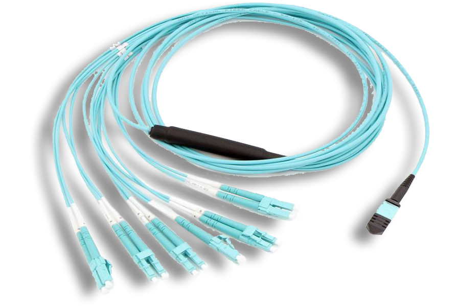
MTP/MPO Harness Assemblies
12/24 MTP/MPO LC Harness Cable Assembly
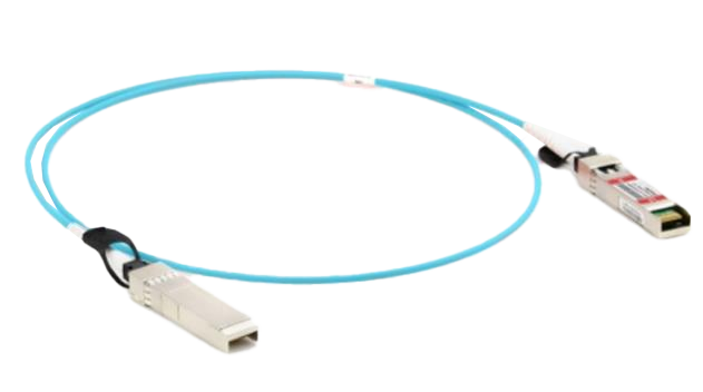
25G SFP28 AOC Cable
25 Gb/s SFP28 Active Optical Cable DDM
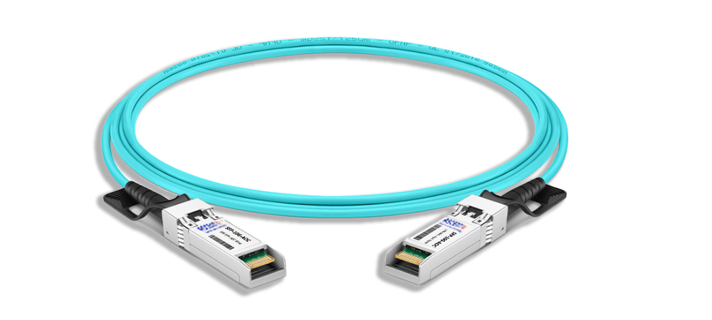
SFPP AT AOC Cable
10G SFP+ Active Optical Cable
100G to 25G Adapter
100G QSFP28 to 25G SFP28 Adapter
10G SFP+ Passive Copper Twinax Cable
SFPP-AT-DAC-2M 10G SFP+ Passive Direct Attach Copper Twinax Cable (PCC)
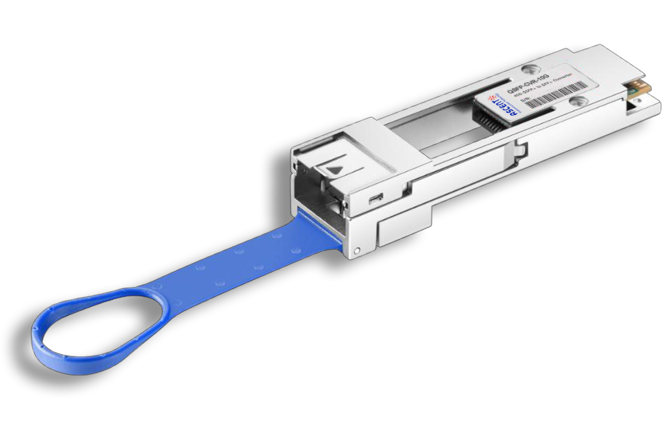
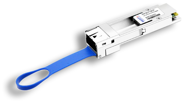
QSFP CVR 10G
QSFP to SFP/SFP+ Adapter Module
White Paper
Press Releases
Briefings 1
Briefings 2
Videos, etc.
QRG
Manual1
Manual2
Get in touch with our experts
Feedback