- FIBER OPTIC TRANSCEIVERS >Optical Cables and Accessories >QSFP AQ LP 31 10 MPO3
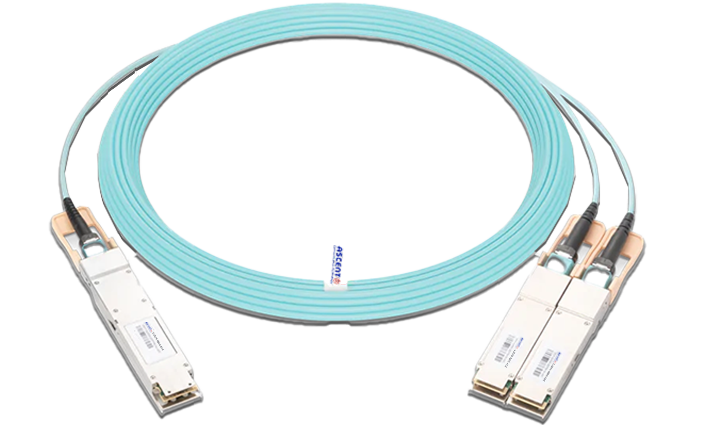
QSFP AQ LP 31 10 MPO3
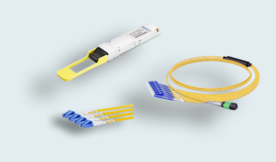
Ascentãs QSFP-AQ-LP-31 QSFP+ 4x10GBase-LR 1310 nm transceiver module kits are designed for use in high density 10 Gigabit Ethernet links over single mode fiber.
ã Hot-pluggable QSFP+ form factor
ã Supports 4 independent streams of 10G Ethernet or OTN data
ã Power dissipation < 2.5 W
ã RoHS-6 compliant
ã Commercial case temperature range 0ô¯C to 70ô¯C
ã Single 3.3 V power supply
ã Maximum link length of 10 km on single-mode fiber (SMF)
ã XLPPI electrical interface
ã MPO12 receptacle
ã Built-in digital diagnostic functions, including Tx/Rx power monitoring
General Product Characteristics
Parameter | Value | Unit | Notes |
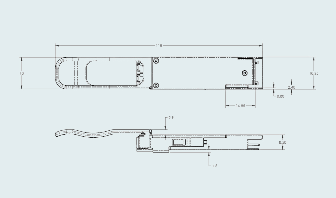
Module Form Factor | QSFP+ | ||
Maximum Aggregate Data Rate | 44.4 | Gb/s | |
Maximum Data Rate per Lane | 11.095 | Gb/s | |
Protocols Supported | 10G Ethernet | This module is not retimed | |
Electrical Interface and Pinãout | 38ãpin edge connector | Pinãout as defined by the QSFP+ MSA | |
Maximum Power Consumption | 2.5 | W | |
Management Interface | Serial, I2Cãbased, 400 kHz maximum frequency | As defined by the QSFP+ MSA | |
Bit Rate per Lane | BR | 9.95 | |
Bit Error Ratio | BER | ||
Link Distance on SMFã28 | d | ||
Bit Rate per Lane | BR | 9.95 |
Notes:
1. Compliant with 10GBASEãLR/LW, OTU2, OTU1e, and OTU2e and XLPPI.
2. Tested with a PRBS 2ã1 test pattern.
Absolute Maximum Ratings
Parameter | Symbol | Min | Typ. | Max | Unit | Notes |
Maximum Supply Voltage | Vcc1, VccTx, VccRx | ã0.5 | 3.6 | V | ||
Storage Temperature | Ts | ã40 | 85 | ô¯C | ||
Case Operating Temperature | Top | 0 | 70 | ô¯C | ||
Relative Humidity | RH | 0 | 85 | % | Nonãcondensing | |
Damage Threshold, per Lane | DT | 3.4 | dBm |
Electrical Characteristics (TOP = 0 ô¯C to 70 ô¯C, VCC = 3.1 V to 3.47 V)
Parameter | Symbol | Min. | Typ. | Max. | Unit | Notes |
Supply Voltage | Vcc1, VccTx, VccRx | 3.1 | 3.47 | V | ||
Supply Current | Icc | 1.13 | A | |||
Transmitter TurnãOn Time | 2000 | ms | 2 | |||
Transmitter (per Lane) | ||||||
Single Ended Input Voltage Tolerance | VinT | ã0.3 | 4.0 | V | ||
Differential Data Input Swing | Vin,pp | 120 | 1200 | mVpp | 3 | |
Differential Input Threshold | 50 | mV | ||||
AC Common Mode Input Voltage Tolerance (RMS) | 15 | mV | ||||
Differential Input Return Loss | Per IEEE P802.3ba, Section 86A.4.1.1 | dB | 4 | |||
J2 Jitter Tolerance | Jt2 | 0.17 | UI | |||
J9 Jitter Tolerance | Jt9 | 0.29 | UI | |||
Data Dependent Pulse Width Shrinkage | DDPWS | 0.07 | UI | |||
Eye Mask Coordinates {X1, X2, Y1, Y2} | 0.11, 0.31 95, 350 | UI mV | 5 | |||
Receiver (per Lane) | ||||||
SingleãEnded Output Voltage | ã0.3 | 4.0 | V | |||
Differential Data Output Swing | Vout,pp | 200 | 400 | mVpp | 6,7 | |
300 | 600 | |||||
400 | 800 | |||||
600 | 1200 | |||||
AC Common Mode Output Voltage (RMS) | 7.5 | mV | ||||
Termination Mismatch at 1 MHx | 5 | % | ||||
Differential Output Return Loss | Per IEEE P802.3ba, Section 86A.4.2.1 | dB | 4 | |||
Common Mode Output Return Loss | Per IEEE P802.3ba, Section 86A.4.2.2 | dB | 4 | |||
Output Transition Time, 20 % To 80 % | 28 | ps | ||||
J2 Jitter Output | Jo2 | 0.42 | UI | |||
J9 Jitter Output | Jo9 | 0.65 | UI | |||
Eye Mask Coordinates #1 {X1, X2, Y1, Y2} | 0.29, 0.5 150, 425 | UI mV | 5 | |||
Power Supply Ripple Tolerance | PSR | 50 | mVpp | |||
Notes:
1. Maximum total power value is specified across the full temperature and voltage
range
2. From powerãon and end of any fault conditions.
3. After internal AC coupling. Selfãbiasing 100öˋ differential input.
4. 10 MHz to 11.1 GHz range
5. Hit ratio = 5 x 10Eã5.
6. AC coupled with 100 öˋ differential output impedance.
7. Output voltage settable in four discrete ranges via I2C command.
Optical Characteristics (TOP = 0 ô¯C to 70 ô¯C, VCC = 3.1 V to 3.47 V)
Parameter | Symbol | Min. | Typ. | Max. | Unit | Notes |
Transmitter | ||||||
Signaling Speed per Lane | 9.95 | 10.095 | GBd | 1 | ||
Lane Center Wavelength | ö£ | 1290 | 1330 | |||
Average Launch Power per Lane | TXPx | ã6.0 | ã1.0 | dBm | 2 | |
Transmit OMA per Lane | TxOMA | ã5.2 | 3.0 | dBm | ||
Transmitter and Dispersion Penalty | TDP | 3.2 | dB | |||
Transmit OMA per Lane Minus TDP | ã6.2 | m | ||||
Optical Extinction Ratio | ER | 6.0 | dB | |||
Sidemode Suppression ratio | SSRmin | 30 | dB | |||
Average Launch Power of OFF Transmitter, per Lane | ã30 | dBm | ||||
Relative Intensity Noise | RIN | ã128 | dB/Hz | 3 | ||
Tx Jitter | Txj | ã20 | dB | |||
Transmitter Reflectance | ã12 | |||||
Transmitter Eye Mask Definition | Per 802.3ae, G.693, and G.691 | |||||
Receiver | ||||||
Signaling Speed per Lane | 9.95 | 10.095 | GBd | 4 | ||
Lane Center Wavelength | ö£ | 1260 | 1355 | |||
Damage Threshold per Lane | PMAX | 1.5 | dBm | |||
Average Receive Power per Lane | RXPx | ã14.4 | 0.5 | dBm | 5 | |
Receiver Sensitivity (OMA) per Lane | Rxsens | ã12.6 | dBm | |||
Stressed Receiver Sensitivity (OMA) per Lane | SRS | ã10.3 | dBm | |||
Return Loss | RL | ã14 | dBm | |||
Receive Electrical 3 dB Upper Cutoff Frequency, per Lane | 12.3 | GHz | ||||
LOS DeãAssert | LOSD | ã14 | dBm | |||
LOS Assert | LOSA | ã30 | ã17 | dBm | ||
LOS Hysteresis | 0.5 | dB | ||||
Notes:
1. Transmitter consists of 4 lasers operating between 9.95 Gb/s and 11.10 Gb/s each.
2. Minimum value is informative.
3. RIN is scaled by 10*log (10/4) to maintain SNR outside of transmitter.
4. Receiver consists of 4 photodetectors operating between 9.95 and 11.10 Gb/s each.
5. Minimum value is informative, equals min TxOMA with infinite ER and max channel insertion loss.
MTP/MPO Breakout Cable
Construction | Description |
Fiber Count | 8ã144 Fibers |
Fiber Mode | Single mode: OS2 9/125ôçm Multimode: OM4 50/125ôçm, OM3 50/125ôçm |
Fiber Brand | Corning ClearCurveôÛ multimode fiber and SMFã28ôÛ Ultra optical fiber |
Connector A | MTP Female, Male; MPO Female, Male |
Connector Brand | US Conec MTPôÛ, Senko MPO |
Connector B | LC, SC, FC, ST |
Polarity | Type A, Type B, Type C |
Cable Jacket Ratings | Plenum (OFNP) Low Smoke Zero Halogen (LSZH) Riser (PVC) |
Color Codes | MTP | MPO | LC |
Cable Jackets | OS2: Yellow OM4: Magenta OM3: Aqua | OS2: Yellow OM4: Magenta OM3: Aqua | OS2: Yellow OM4: Magenta OM3: Aqua |
Connectors | OS2: Green OM4/OM3: Aqua | OS2: Green OM4/OM3: Aqua | Single Mode: UPC Blue, APC Green Multimode: Beige |
Boots | 8 Fibers: Grey 12 Fibers: Black 24 Fibers: Red | 8/12/24 Fibers: Black | Single Mode: UPC Blue, APC Green Multimode: Beige |
Physical Properties | Description |
Cable Diameter | 3.0mm |
Breakout Leg | 2.0/0.9mm |
Breakout Length | 0.5/0.3m |
Minimum Bend Radius | Single Mode: 10.0mm, Multimode: 7.5mm |
Operating Temperature | ã10ô¯C to +70ô¯C |
Storage Temperature | ã40ô¯C to +85ô¯C |
Construction | Description | |
Wavelength (nm) | Single Mode: 1310/1550 Multimode: 850/1300 | |
Transmission Distance | OM4: 150m at 40/100G, 400m at 10G OM3: 100m at 40/100G, 300m at 10G | |
Connector | MTP/MPO | |
Fiber Mode | Single Mode | Multimode |
Attenuation (dB/km) | ãÊ0.32 at 1310nm ãÊ0.18 at 1550nm | ãÊ2.3 at 850nm ãÊ0.6 at 1300nm |
Insertion Loss (dB) | ãÊ0.35 | ãÊ0.35 |
Return Loss (dB) | APC: ãË60, UPC: ãË50 | UPC: ãË20 |
Connector | LC/SC/FC/ST | |
Fiber Mode | Single Mode | Multimode |
Insertion Loss (dB) | APC: ãÊ0.3, UPC: ãÊ0.2 | UPC: ãÊ0.2 |
Return Loss (dB) | APC: ãË65, UPC: ãË50 | UPC: ãË30 |
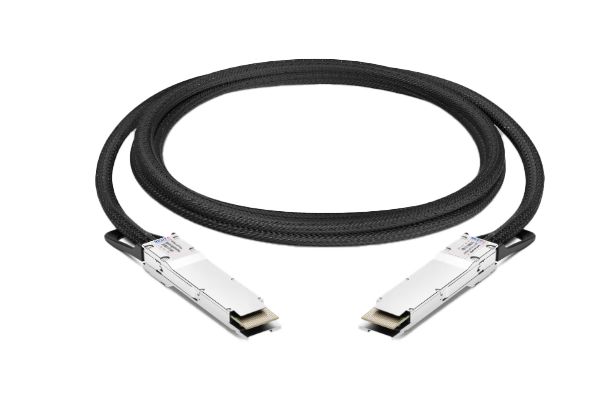
OSFP 800G DAC Cable
800G Twin-port 2x400G OSFP Passive DAC Cable
OSFP 800G ACC Cable
800G Twin-port 2x400G OSFP Active Copper Cable
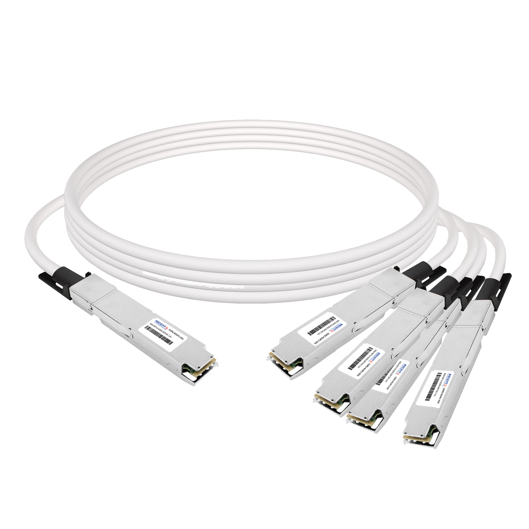
800G OSFP to 4xOSFP DAC Cable
800G IB NDR OSFP to 4xOSFP RHS Hairtail+ Direct Attach Copper Cable
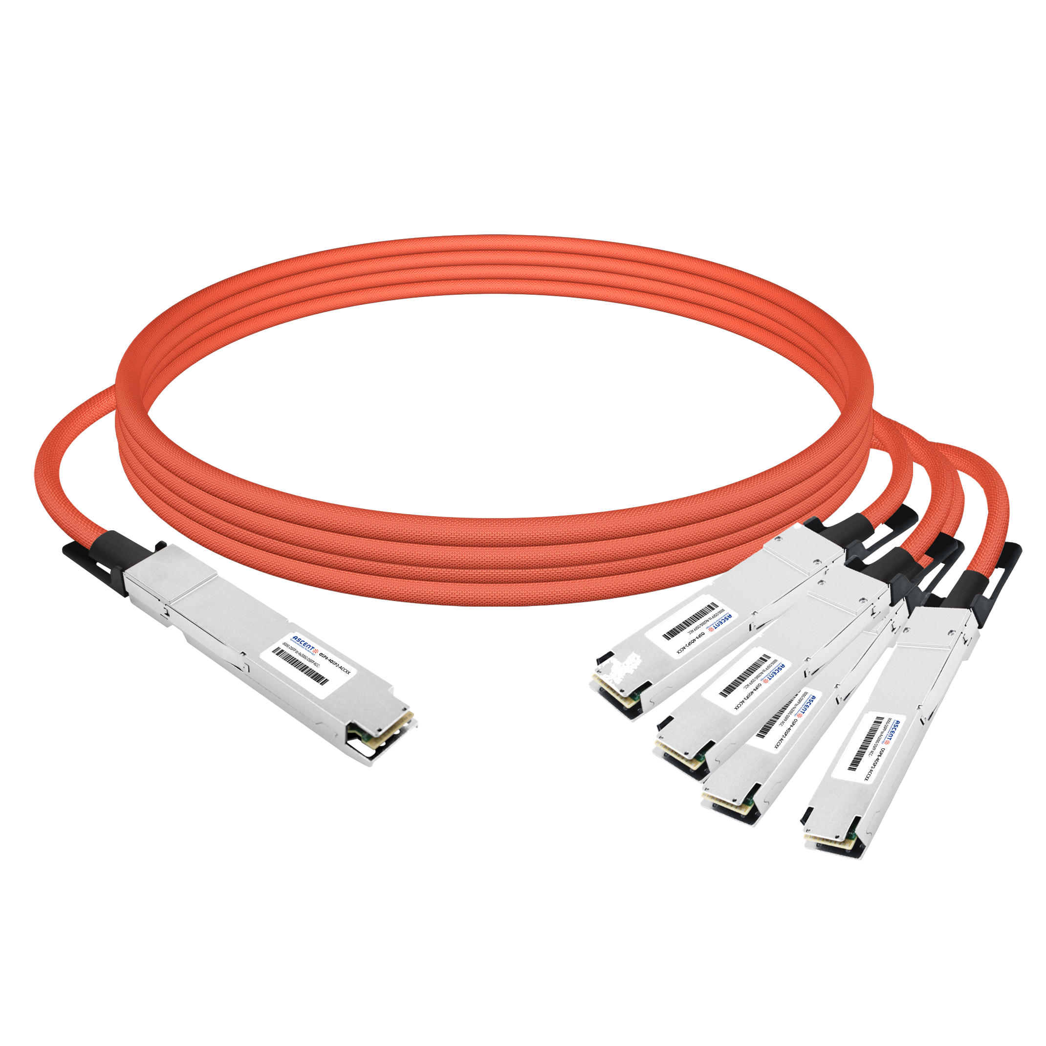
800G OSFP to 4x200G Breakout ACC
800G 4x200G OSFP Breakout Active Copper Cable
800G OSFP 4xQSFP112 DAC Cable
800G OSFP to 4xQSFP112 Cable Assembly
800G QSFP Q112 AEC Cable
800G QSFP-DD to QSFP-DD Active Electrical Cable

400G OSFP to 400G QSFP-DD DAC
400G OSFP to 400G QSFP-DD Passive DAC Twinax Cable

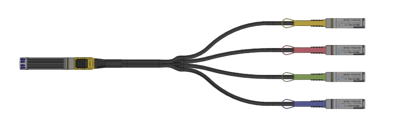
400G OSFP to 4x100G QSFP56 DAC
400G OSFP to 4x100G QSFP56 Passive DAC Breakout Cable
400G OSFP to 2x200G QSFP56 AOC Breakout Cable
400G OSFP to 2x200G QSFP56 AOC Breakout Cable
400G QSFP Q112 AEC Cable
400G QSFP-DD to QSFP-DD Active Electrical Cable

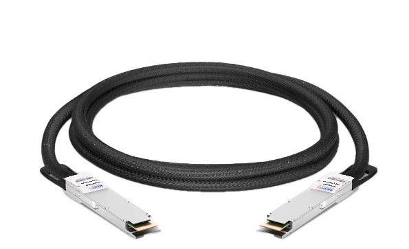
400G QSFP DD DAC Cable
400G QSFP-DD Passive Direct Attach Copper Cable

400G QSFP DD to 4X100G QSFP56 AOC
400G QSFP-DD to 4x100G QSFP56 Active Optical Cable

400G QSFP DD to 4X100G QSFP28 AOC
400G QSFP-DD to 4x100G QSFP28 Active Optical Cable

400G QSFP DD AOC Cable
400G QSFP-DD Active Optical Cable
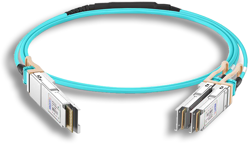
400G QSFP DD AOC Breakout Cable
400G QSFP-DD to 2x 200G QSFP56 Active Optical Breakout Cable

200G QSFP56 InfiniBand HDR AOC
200G QSFP56 to QSFP56 Active Optical Cable

200G QSFP56 PSM4 DAC
200G QSFP56 PSM4 Direct Attach Passive Copper Cables
QSFP28 100G AOC Cable
100 Gb/s QSFP28 Active Optical Cable
QSFP28 100G DAC Cable
100G QSFP28 Passive DAC Twinax Cable
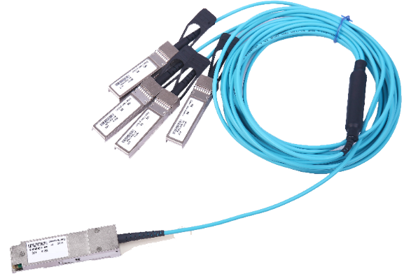
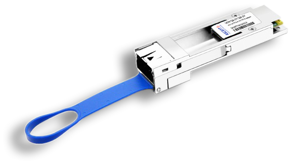
QSFP AQ AOC 4G 10
40G QSFP+ to 4x10G SFP+ Transceiver

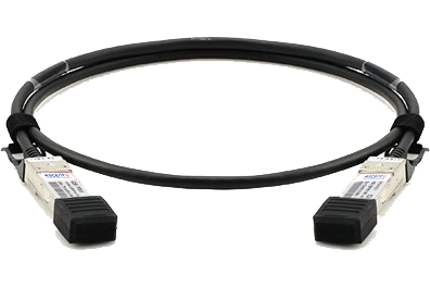
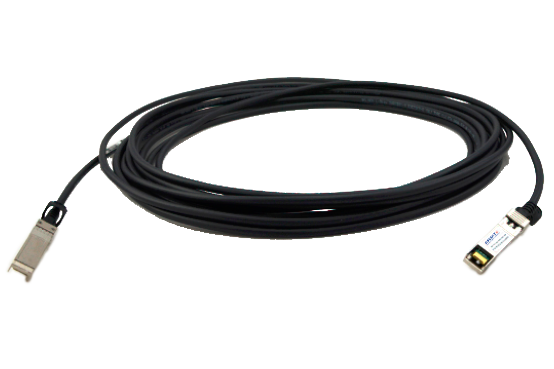
QSFP+ 40G DAC Cable
40G QSFP+ to QSFP+ Passive Copper Cable (PCC)
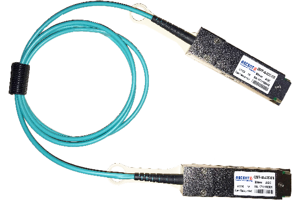
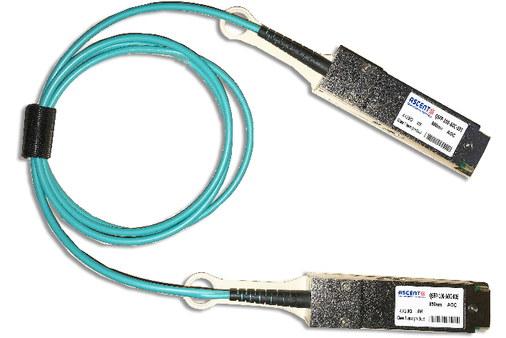
QSFP+ 40G AOC Cable
40G QSFP+ Active Optical Cable
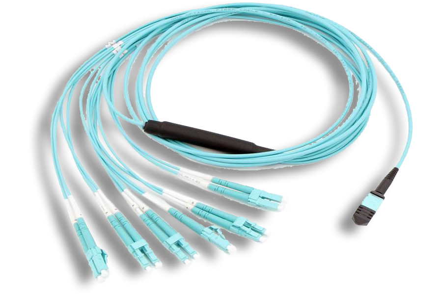
MTP/MPO Harness Assemblies
12/24 MTP/MPO LC Harness Cable Assembly
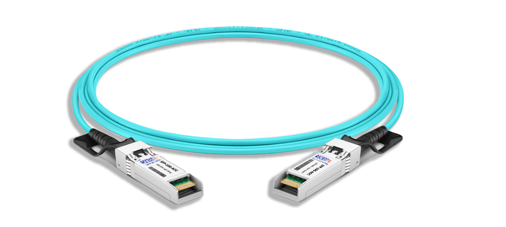
25G SFP28 AOC Cable
25 Gb/s SFP28 Active Optical Cable DDM
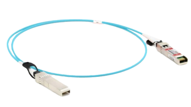
SFPP AT AOC Cable
10G SFP+ Active Optical Cable
100G to 25G Adapter
100G QSFP28 to 25G SFP28 Adapter
10G SFP+ Passive Copper Twinax Cable
SFPP-AT-DAC-2M 10G SFP+ Passive Direct Attach Copper Twinax Cable (PCC)
White Paper
Press Releases
Briefings 1
Briefings 2
Videos, etc.
QRG
Manual1
Manual2
Get in touch with our experts
Feedback