- FIBER OPTIC TRANSCEIVERS >10G Transceivers >10GBASE-T SFP+ Copper RJ45 30 m
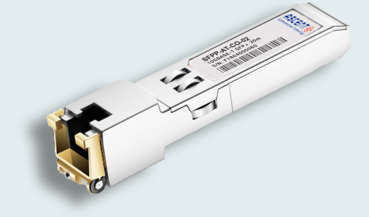
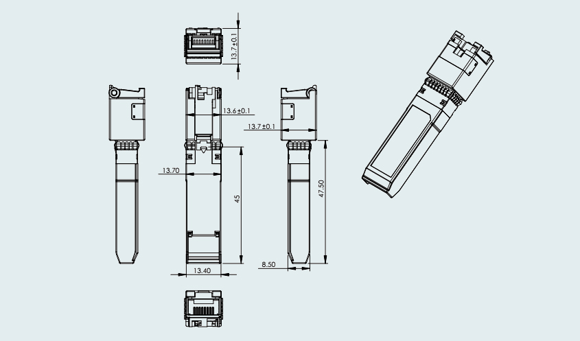
10GBASE-T SFP+ Copper RJ45 30 m
Ascentãs SFPP-AT-CO-02 10GBASE-T SFP+ copper transceivers are based on the SFP Multi-Source Agreement (MSA). These 10GBASE SFP+ series modules offer a wide variety of 10 Gigabit Ethernet connectivity options for data center, enterprise wiring closet, and service provider transport applications.
ã Up to 10 Gb/s bi-directional data links
ã Hot-pluggable SFP+ footprint
ã Low power dissipation (max. 3W)
ã Compact RJ-45 connector assembly
ã Fully metal enclosure, for lower EMI
ã RoHS compliant and lead-free
ã Single +3.3V power supply
ã Supports Links up to 30m using Cat 6a/7 Cable
ã Case operating temperature: 0 ô¯C to +70 ô¯C
+3.3V Volt Electrical Power Interface
SFPPãATãCOã02 has an input voltage range of 3.3 V +/ã 5%. The 4V maximum voltage is not allowed for continuous operation.
Parameter | Symbol | Min. | Typ. | Max. | Unit | Note |
Supply Current | Is | 700 | 900 | mA | 1 | |
Input Voltage | Vcc | 3.13 | 3.3 | 3.47 | V | |
Maximum Voltage | Vmax | 4 | V | |||
Surge Current | Isurge | TBD | mA |
Notes:
1. 3.0W max power over full range of voltage and temperature. See caution note below.
2. Referenced to GND.
3. Hot plug above steady state current. See caution note below.
Caution: Power consumption and surge current are higher than the specified values in the SFP MSA
LowãSpeed Signals, Electronic Characteristics
MOD_DEF(1) (SCL) and MOD_DEF(2) (SDA), are open drain CMOS signals (see section VII, "Serial Communication Protocol"). Both MOD_DEF(1) and MOD_DEF(2) must be pulled up to host_Vcc.
Parameter | Symbol | Min. | Max. | Unit | Note |
SFP Output LOW | VOL | 0 | 0.5 | V | 1 |
SFP Output HIGH | VOH | host_Vcc ã0.5 | host_Vcc + 0.3 | V | 1 |
SFP Input LOW | VIL | 0 | 0.8 | V | 2 |
SFP Input HIGH | VIH | 2 | Vcc + 0.3 | V | 2 |
Notes:
1. 4.7 köˋ to 10 köˋ pullãup to host_Vcc, measured at host side of connector.
2. 4.7 köˋ to 10 köˋ pullãup to Vcc, measured at SFP side of connector.
HighãSpeed Electrical Interface
All highãspeed signals are ACãcoupled internally.
HighãSpeed Electrical Interface, Transmission LineãSFP | ||||||
Parameter | Symbol | Min. | Typ. | Max. | Unit | Note |
Line Frequency | fL | 125 | MHz | 1 | ||
Tx Output Impedance | Zout, TX | 100 | öˋ | 2 | ||
Rx Input Impedance | Zin, RX | 100 | öˋ | 2 | ||
HighãSpeed Electrical Interface, HostãSFP | ||||||
Parameter | Symbol | Min. | Typ. | Max. | Unit | Note |
Single ended data input swing | Vinsing | 250 | 1200 | mV | 3 | |
Single ended data output swing | Voutsing | 350 | 800 | mV | 3 | |
Tx Input Impedance | Zin | 50 | öˋ | 3 | ||
Rx Output Impedance | Zout | 50 | öˋ | 3 | ||
Notes:
1. 5ãlevel encoding, per IEEE 802.3.
2. Differential, for all frequencies between 1 MHz and 125 MHz.
3. Singleãended.
General Specifications
Clock tolerance is +/ã 50 ppm
Automatic crossover detection is enabled. External crossover cable is not required
Parameter | Symbol | Min. | Typ. | Max. | Unit | Note |
Data Rate | BR | 1 | 10 | Gb/sec | 1 | |
Cable Length | L | 30 | m | 2 |
Notes:
1. IEEE 802.3 compatible. By default, the SFPPãATãCOã02 is a full duplex device in preferred master mode.
2. Category6A/7 UTP. BER.
Environmental Specifications
Parameter | Symbol | Min. | Typ. | Max. | Unit | Note |
Case Operating Temperature | Tcase | 0 | 70 | ô¯C | ||
Storage Temperature | Tsto | ã40 | 85 | ô¯C | Ambient temperature |
Serial Communication Protocol
SFPPãATãCOã02 supports the 2ãwire serial communication protocol outlined in the SFP MSA. These SFPs use an MCU, can be accessed with address of A0h.
Serial Bus Timing Requirements | ||||||
Parameter | Symbol | Min. | Typ. | Max. | Unit | Note |
I 2C Clock Rate | 0 | 200, 000 | Hz | |||
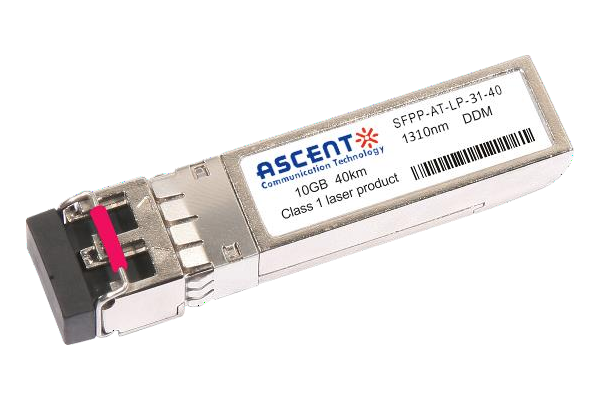
10G SFP+ LR 1310 nm 40 km
10 Gb/s 1310nm SFP+ 40 km Transceiver

10G SFP+ LR 1310 nm 20 km
SFPP-ATLP-31-20 SFP+ Plug-in, 10Gbps, 20km, TX=1310/RX wide, on two single mode fibers, LC/PC Blue
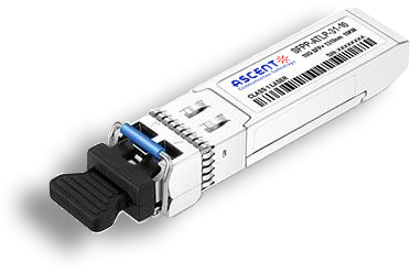
10G SFP+ LR 1310 nm 10 km
SFPP-ATLP-31-10 SFP+ Plug-in, 10Gbps, 10km, TX=1310/RX wide, on two single mode fibers, LC/PC Blue

10G SFP+ LRM 1310 nm 2 km
SFPP-ATLP-31-02 10Gb/s 1310nm SFP+ 2 km Transceiver
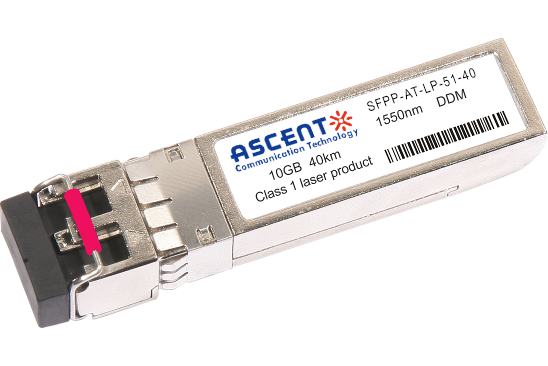
10G SFP+ ER 1550 nm 40 km
SFPP-ATLP-51-40 10 Gb/s 1550 nm SFP+ 40 km Transceiver
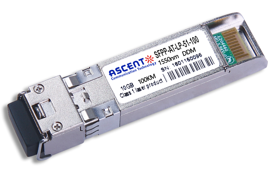
10G SFP+ CDR 1550 nm 100 km
SFPP-ATLP-51-100 10 Gb/s 1550 nm SFP+ 100 km Transceiver
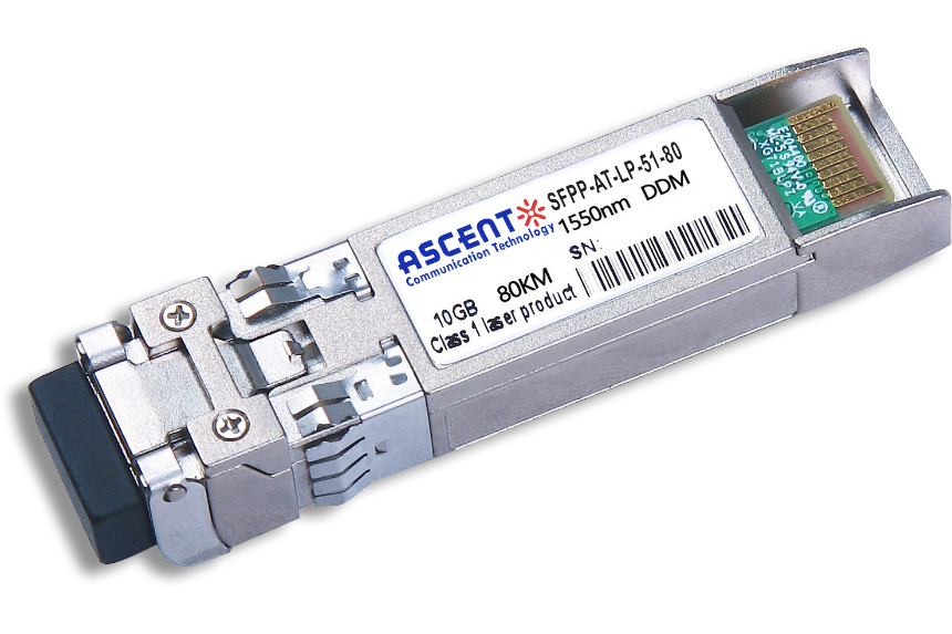
10G SFP+ ZR 1550 nm 80 km
SFPP-ATLP-51-80 10 Gb/s 1550 nm SFP+ 80 km Transceiver
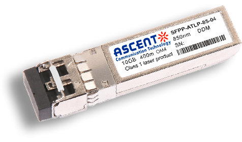
10G SFP+ 850 nm 400 m
10 Gb/s 850nm Multi-mode SFP+ Transceiver 400m
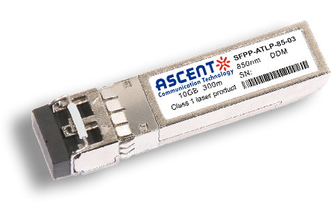
10G SFP+ 850 nm 300 m
SFPP-ATLP-85-03 10 Gb/s 850nm Multi-Mode SFP+ Transceiver
10G SFP+ Tunable DWDM 80 km
SFPP-LP-T99R-80 10 Gb/s Tunable DWDM SFP+ 80 km Transceiver
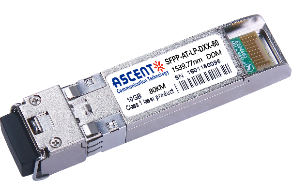
10G SFP+ DWDM 80 km
SFPP-ATLP-DXX-80 10 Gb/s DWDM SFP+ 80 km Transceiver
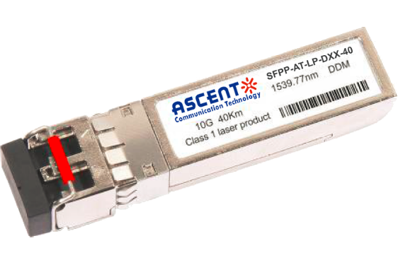
10G SFP+ DWDM 40 km
SFPP-ATLP-DXX-40 SFP+ Plug-in, 10Gbps, 40km, TX=ITU Ch xx (17 to 61) /RX wide, on two single mode fibers, LC/PC Blue
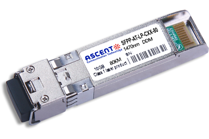
10G SFP+ CWDM 80 km
SFPP-ATLP-CXX-80 SFP+ Plug-in, 10 Gbps, 80 km, TX = CWDM Ch xx (1470ô nm to 1610 nm)/RX wide, on two single-mode fibers, LC/PC Blue.
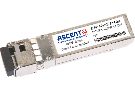
10G SFP+ CWDM 2733 60 km
SFPP-AT-LP-XXXX-60D 10 Gb/s BIDI SFP+ 60 km Transceiver
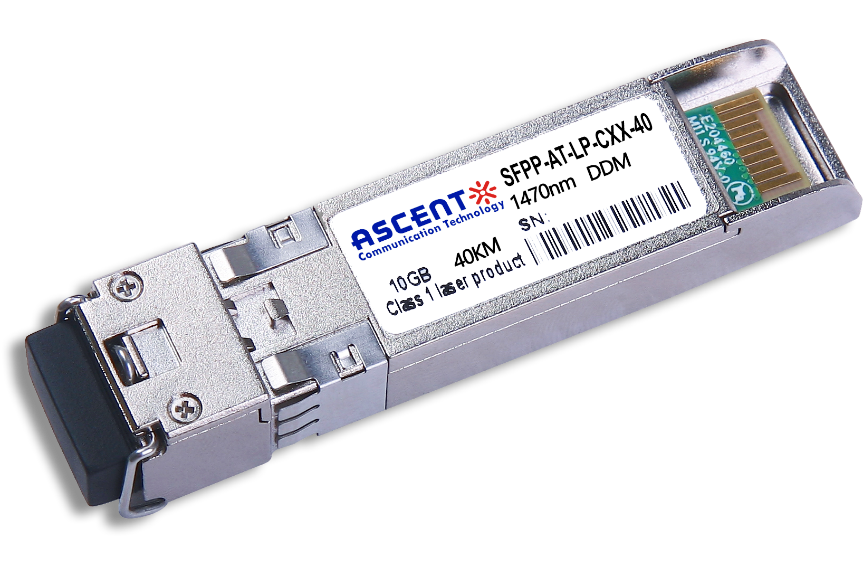
10G SFP+ CWDM 40 km
SFPP-ATLP-CXX-40 SFP+ Plug-in, 10Gbps, 40km, TX=CWDM Ch xx (1270ô nm to 1610 nm) /RX wide, on two single mode fibers, LC/PC Blue
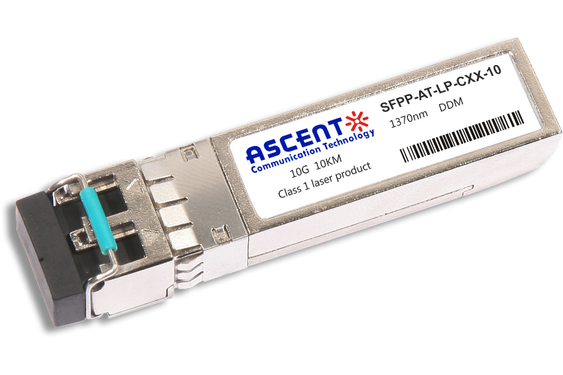
10G SFP+ CWDM 10 km
SFPP-ATLP-CXX-10 SFP+ Plug-in, 10 Gbps, 10 km, TX=CWDM Ch xx (1270 nm to 1610 nm)/RX wide, on two single-mode fibers, LC/PC Blue
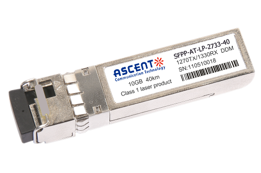
10G SFP+ CWDM 2733 40 km
SFPP-AT-LP-XXXX-40 SFP+ Plug-in, 10Gbps, 40km, TX=1270/RX=1330 , on one single mode fibers, LC/PC Blue
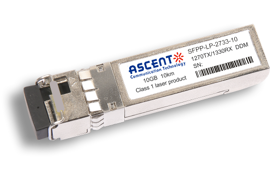
10G SFP+ CWDM 2733 10 km
SFPP-LP-XXXX-10 SFP+ Plug-in, 10Gbps, 10km, TX=1270/RX=1330 , on one single mode fibers, LC/PC Blue

10G XFP BIDI 80KM
XFP 10 Gb/s BIDI Single-Mode 80 km Transceiver DDM

10G XFP BIDI 40KM
XFP 10 Gb/s BIDI Single-Mode 40 km Transceiver DDM

10G XFP BIDI 20KM
XFP 10 Gb/s BIDI Single-Mode 20 km Transceiver DDM

10G XFP BIDI 10KM
XFP 10 Gb/s BIDI Single-Mode 10 km Transceiver DDM

10G XFP LR 1310 nm 20 km
XFP-AT-LP-31-20 10 Gb/s 20 km XFP Transceiver

10G XFP LR 1310 nm 10 km
XFP-AT-LP-31-10 10 Gb/s 10 km XFP Transceiver
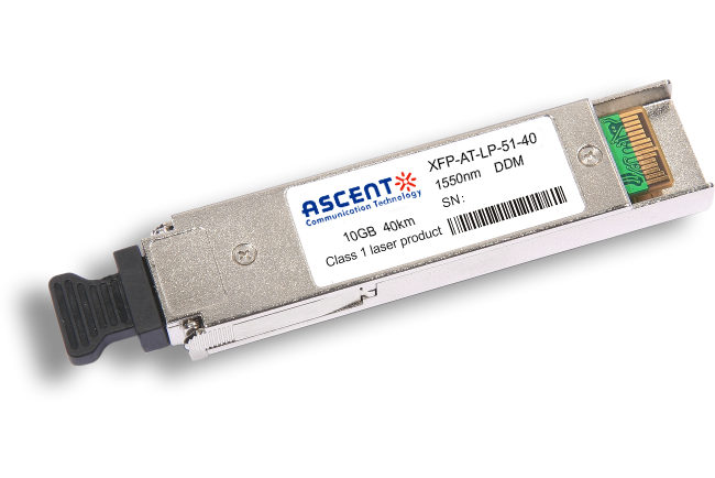
10G XFP ER 1550 nm 40 km
XFP-AT-LP-51-40 10 Gb/s 40 km XFP Optical Transceiver

10G XFP ZR 1550 nm 80 km
XFP-AT-LP-51-80 10 Gb/s 80 km XFP Optical Transceiver
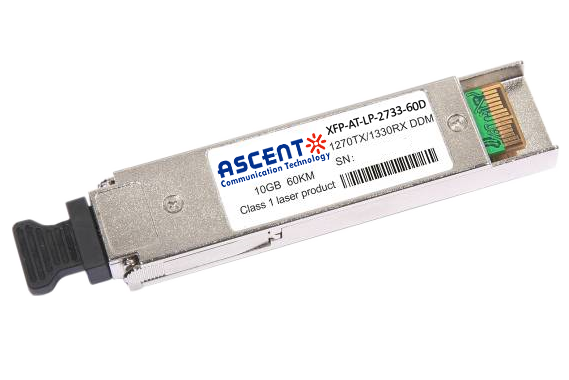
10G XFP CWDM 2633 60 km
XFP-ATLP-XXXX-60 10 Gb/s BIDI XFP 60 km Transceiver
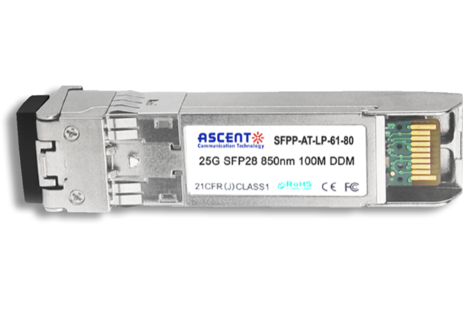
10G SFP+ CWDM 1610 80 km
SFPP-ATLP-61-80 SFP+ Plug-in, 10Gbps, 80km, TX=1610/RX wide, on two single mode fibers, LC/PC Blue
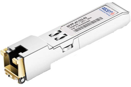
10G SFP+ Copper RJ45 30 m
SFPP-AT-CO-03 10GBASE-T SFP+ Copper RJ45 30m Transceiver

10G X2 850nm 300m
X2 10Gb/s 850nm Multi-mode Transceiver 300m
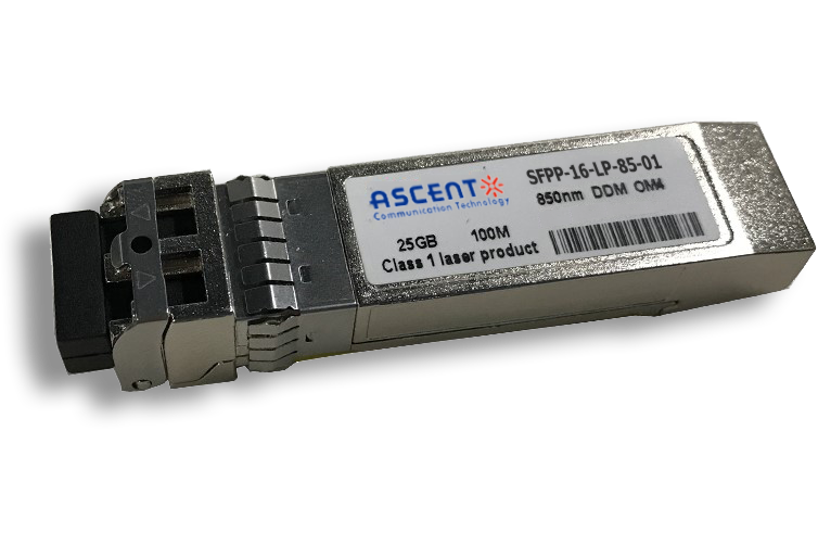
16G SFP+ FC 850 nm 100 m
SFPP-16-LP-85-01 16 Gb/s 850 nm SFP+ 100 m Transceiver
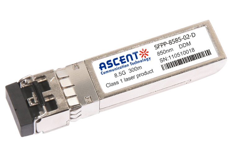
8.5G SFP+ SR 850 nm 150 m
SFPP-A8LP-85-015 8.5 Gb/s 850 nm Multi-Mode SFP+ Transceiver
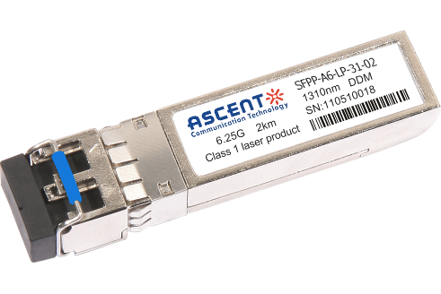
6.25G SFP+ LRM 1330 nm 2 km
SFPP-A6-LP-31-02 6.25 Gb/s Single-Mode SFP+ Transceiver
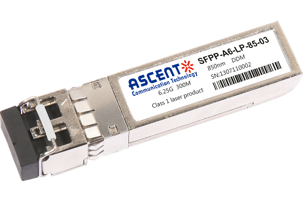
6.25G SFP+ SR 850 nm 300 m
SFPP-A6-LP-85-03 6.25 Gb/s 850 nm Multi-Mode SFP+ Transceiver
Datasheet
White Paper
Press Releases
Briefings 1
Briefings 2
Videos, etc.
QRG
Manual1
Manual2
Get in touch with our experts
Feedback