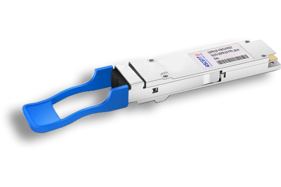
- FIBER OPTIC TRANSCEIVERS >200G & 100G Transceivers >100G QSFP28 LR Single ö£ 10 km
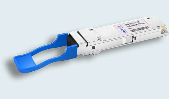
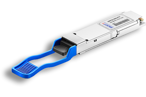
100G QSFP28 LR Single ö£ 10 km
Ascentãs QSFP28 100G LR1 Ethernet module is a transceiver module designed for 10km optical communication applications, and it is compliant with IEEE 802.3cd and QSFP28 MSA standard.
ãÂô ô ô Compliant with QSFP28 Standard: SFF-8636 Rev 2.10a
ãÂô ô ô Compliant with IEEE802.3cu D3.2 100GBASE-LR1
ãÂô ô ô High speed I/O electrical interface (CAUI-4)
ãÂô ô ô Single 3.3V Supply Voltage
ãÂô ô ô Maximum power consumption 4.5W
ãÂô ô ô 0-70 ô¤C Case Operating Temperature
ãÂô ô ô 1311nm EML laser and PIN Receiver
ãÂô ô ô Hermetically sealed TO Based design
ãÂô ô ô QSFP28 MSA package with duplex LC connector
ãÂô ô ô Two Wire Serial Interface with Digital Diagnostic Monitoring
ãÂô ô ô KP4 FEC termination inside module
ãÂô ô ô Supporting 10km reach of single mode fiber
ãÂô ô ô Complies with EU Directive 2011/65/EU (RoHS compliant)
ãÂô ô ô Class 1 Laser
Parameter | Symbol | Min. | Typ. | Max. | Unit | Notes |
Storageô Temperature | TS | ã40 | ã | +85 | ô¤C | |
Supplyô Voltage | VCC | ã0.3 | ã | 3.6 | V | |
Relativeô Humidityô (NonãCondensing) | RH | 5 | ã | 95 | % | |
Dataô Inputô Voltageô ãô Differential | |VDIPãVDIN| | ã | ã | 1.0 | V | |
Controlô Inputô Voltage | VI | ã0.3 | ã | Vcc+0.3 | V | |
Controlô Outputô Current | IO | ã20 | ã | 20 | mA |
ô
Recommendedô Operatingô Conditions
Parameter | Symbol | Min. | Typ. | Max. | Unit | Note |
Operatingô Caseô Temperature | TOPR | 0 | ã | 70 | ô¯C | |
Powerô Supplyô Voltage | VCC | 3.135 | 3.3 | 3.465 | V | |
Instantaneousô Peakô Currentô atô Hotô Plug | ICC_IP | ã | ã | 1800 | mA | |
Sustainedô Peakô Currentô atô Hotô Plug | ICC_SP | ã | ã | 1485 | mA | |
Maximumô Powerô Dissipation | PD | ã | ã | 4.5 | W | 1 |
Maximumô Powerô Dissipation,ô Lowô Powerô Mode | PDLP | ã | ã | 1.5 | W | |
Signalingô Rate | SR | ã | 53.125 | ã | GBd | |
Controlô Inputô Voltageô High | VIH | VCC*0.7 | ã | VCC+0.3 | V | |
Controlô Inputô Voltageô Low | VIL | ã0.3 | ã | VCC*0.3 | V | |
Twoô Wireô Serialô Interfaceô Clockô Rate | ã | ã | ã | 400 | kHz | |
Powerô Supplyô Noise | ã | ã | ã | 66 | mVpp | 2 |
Rxô Differentialô Dataô Outputô Load | ã | ã | 100 | ã | ohms | |
Operatingô Distance | ã | 2 | ã | 10000 | m |
Notes:
1.ô Withô powerô supplyô voltageô 3.3ô V.
2.ô 10Hzô ã10MHz
ô
ô ô Opticalô andô Electricalô Characteristics
Parameter | Symbol | Min. | Typ. | Max. | Unit | Note |
Transmitter | ||||||
Wavelength | ö£C | 1304.5 | 1311 | 1317.5 | nm | |
Sideô Modeô Suppressionô Ratio | SMSR | 30 | ã | ã | dB | |
Averageô Opticalô Launchô Power | POUT | ã1.9 | ã | 4.8 | dBm | 1 |
Averageô Launchô Powerô ofô OFFô Transmitter | POUT_OFF | ã | ã | ã15 | dBm | |
Extinctionô Ratio | ER | 3.5 | ã | ã | dB | |
Outerô Opticalô Modulationô Amplitude | OMAouter | ã | ã | 5 | dBm | |
Outerô Opticalô Modulationô Amplitude ô ô forô TDECQô <1.4ô dB ô ô forô 1.4ô dBô ãÊTDECQô ãÊ3.4ô dB | OMAouter | ô 1.1 ã0.3+ô TDECQ | ô ã ã | ô ã ã | ô dBm dBm | |
Transmitterô andô Dispersionô Eyeô Closure | TDECQ | ã | ã | 3.4 | dB | |
Transmitterô eyeô closureô forô PAM4 (TECQ) | TECQ | ô ã | ô ã | ô 3.4 | ô dB | |
|TDECQô ãô TECQ| | ã | ã | ã | 2.5 | dB | |
Over/UnderãShoot | ã | ã | ã | 22 | % | |
Transmitterô Powerô Excursion | ã | ã | ã | 2.8 | dBm | |
RIN15.6OMA | RIN | ã | ã | ã136 | dB/Hz | |
Opticalô returnô lossô tolerance | ORLT | ã | ã | 15.6 | dB | |
Transmitterô transitionô time | ã | ã | 17 | ps | ||
Transmitterô reflectance | TR | ã | ã | ã26 | dB | |
Receiver | ||||||
Wavelength | ö£C | 1304.5 | 1311 | 1317.5 | nm | |
Damageô Threshold | 5.8 | ã | ã | dBm | ||
Averageô Receiveô Power | ã8.2 | ã | 4.8 | dBm | 2 | |
Receiveô Powerô (OMAouter) | RP | ã | ã | 5 | dBm | |
Receiverô Reflectance | RR | ã | ã | ã26 | dB | |
Receiverô Sensitivityô (OMAouter) ô ô forô TECQô <ô 1.4ô dB ô ô forô 1.4ô dBãÊô TECQô ãÊ3.4ô dB | RS | ô ã ã | ô ã ã | ô ã6.1 ã7.5+ô TECQ | ô dBm dBm | |
Stressedô Receiverô Sensitivity | SRS | ã | ã | ã4.1 | dBm | 3 |
Stressedô Receiverô Sensitivityô Testô Conditions | ||||||
Stressedô eyeô closureô forô PAM4ô (SECQ) | SECQ | ã | ã | 3.4 | dB | |
Notes:
1.ô Averageô launchô powerô isô informativeô andô notô theô principalô indicatorô ofô signalô strength.
2.ô Averageô receiveô powerô (min)ô isô informativeô andô notô theô principalô indicatorô ofô signalô strength.
3.ô Measuredô withô conformanceô testô signalô atô TP3ô forô theô BERô =ô 2.4ô xô 10ã4.
ô
ô Electricalô Specificationsô Highô Speedô Signal
Compliantô withô IEEEô 802.3ô CAUIã4
Parameter | Symbol | Min. | Typ. | Max. | Unit | Note |
Receiverô (Moduleô Output) | ||||||
ACô CommonãModeô Outputô Voltageô (RMS) | ã | ã | 17.5 | mV | ||
Differentialô Outputô Voltage | ã | ã | 900 | mV | ||
Eyeô Width | 0.57 | ã | ã | UI | ||
Eyeô Heightô Differential | 228 | ã | ã | mV | ||
Verticalô Eyeô Closure | ã | ã | 5.5 | dB | ||
Differentialô Terminationô Mismatch | ã | ã | 10 | % | ||
Transitionô Timeô (20%ô toô 80%) | 12 | ã | ã | ps | ||
DCô Commonô Modeô Voltage | ã350 | ã | 2850 | mV | ||
Transmitterô (Moduleô Input) | ||||||
Differentialô pkãpkô Inputô Voltageô Tolerance | 900 | ã | ã | mV | ||
Differentialô Terminationô Mismatch | ã | ã | 10 | % | ||
SingleãEndedô Voltageô Toleranceô Range | ã0.4 | ã | 3.3 | V | ||
DCô Commonô Modeô Voltage | ã350 | ã | 2850 | mV | ||
ô
Electricalô Specificationô Lowô Speedô Signal
Compliantô withô SFFã8679ô Revô 1.8
Parameter | Symbol | Min. | Max. | Unit | Condition |
Moduleô Outputô SCLô andô SDA | VOL | 0 | 0.4 | V | |
VOH | Vccã0.5 | Vcc+0.3 | V | ||
Moduleô Inputô SCLô andô SDA | VIL | ã0.3 | Vcc*0.3 | V | |
VIH | Vcc*0.7 | Vcc+0.5 | V | ||
LPMode/TxDis,ô ResetL,ô andô ModSelL | VIL | ã0.3 | 0.8 | V | |
VIH | 2 | Vcc+0.3 | V | ||
ModPrsLô andô IntL/RxLOSL | VOL | 0 | 0.4 | V | |
VOH | Vccã0.5 | Vcc+0.3 | V |
Digitalô Diagnostics
Parameter | Range | Accuracy | Unit | Calibration |
Temperature | 0ô toô 70 | ôÝ3 | ô¯C | Internal |
Voltage | 0ô toô VCC | ôÝ3% | V | Internal |
Txô Biasô Current | 0ô toô 100 | ôÝ10% | mA | Internal |
Txô Outputô Power | ã1.9ô toô +4.8 | ôÝ3 | dB | Internal |
Rxô Receiveô Power | ã8.2ô toô +4.8 | ôÝ3 | dB | Internal |

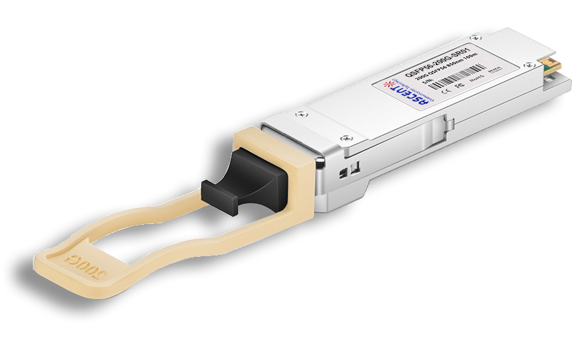
200G QSFP56 SR4 850 nm 100 m
QSFP56-200G-SR01 200 Gb/s QSFP56 SR4 850 nm 100 m Transceiver
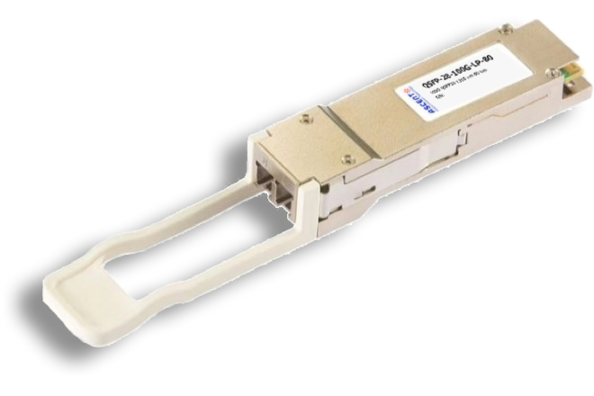
100G QSFP28 ZR4 1310 nm 80 km
QSFP28-100G-LP80 QSFP28 100 Gbps ZR4 Transceiver
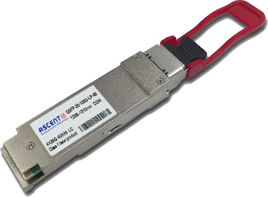
100G QSFP28 ER4 1310 nm 40 km
QSFP28-100G-LP40 100 Gb/s 40 km QSFP28 ER4 Lite Transceiver
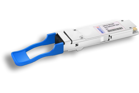
100G QSFP28 LR4 1310 nm 10 km
QSFP28-100G-LP10 100 Gb/s 10km QSFP28 LR4 Transceiver
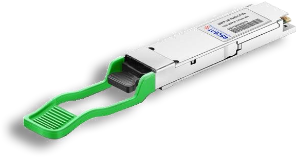
100G QSFP28 CWDM4 1310 nm 2 km
QSFP28-100G-LP02 QSFP28 100 Gbps CWDM4 Transceiver

100G QSFP28 PSM4 1310 nm 2 km
QSFP28-100G-PSM4 100 Gb/s 1310 nm 2 km Transceiver
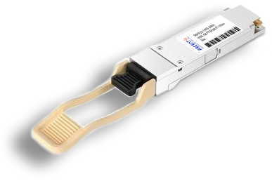
100G QSFP28 SR4 850 nm 100 m
QSFP28-100G-SR01 100 Gb/s SR4 850 nm 100 m Transceiver
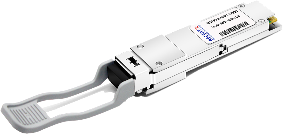
100G QSFP28 SR01 BIDI MMF 850nm 100m
QSFP28 BIDI 100 Gb/s SR Transceiver
100G QSFP28 FR Single ö£ 1310 nm 2 km
QSFP28-100G-FR02 FR1 1310 nm 2 km Transceiver
100G QSFP28 DR Single ö£ 500 m
QSFP28-100G-DR5 DR1 1310 nm 500 m Transceiver
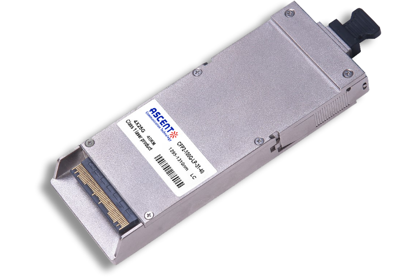
100G CFP2 ER4 40 km
CFP2-LP-31-40 100 Gb/s CFP2 ER4 40 km Transceiver
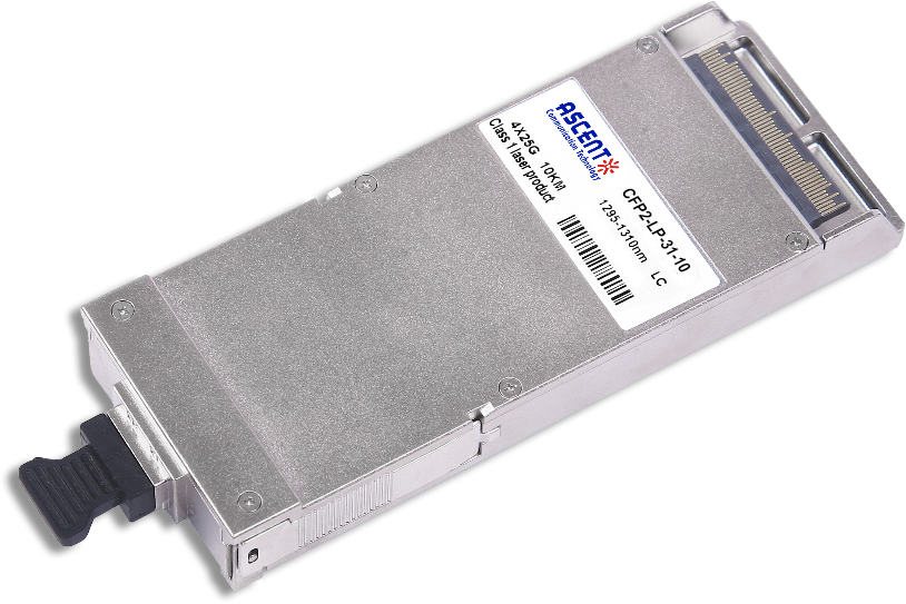
100G CFP2 LR4 10 km
CFP2-LP-31-10 100 Gb/s CFP2 LR4 10 km Transceiver
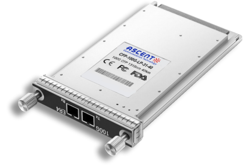
100G CFP ER4 40 km
CFP-LP-31-40 100 Gb/s CFP ER4 40 km Transceiver
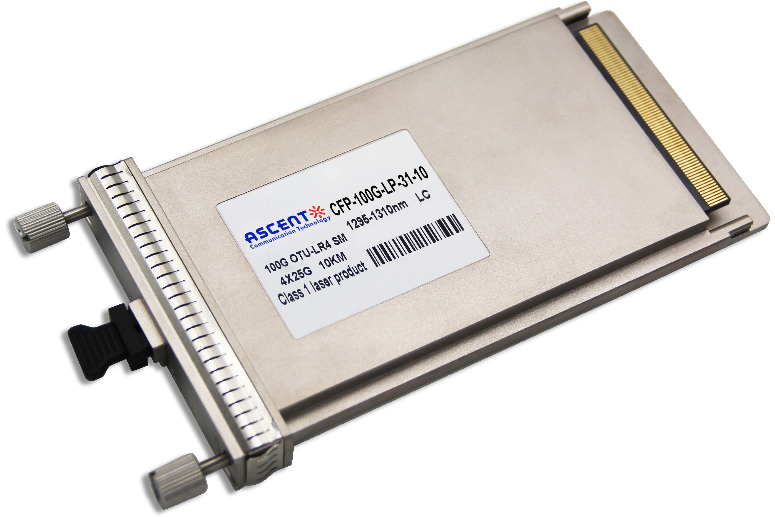
100G CFP LR4 10 km
CFP-LP-31-10 100 Gb/s CFP LR4 10 km Transceiver
White Paper
Press Releases
Briefings 1
Briefings 2
Videos, etc.
QRG
Manual1
Manual2
Get in touch with our experts
Feedback