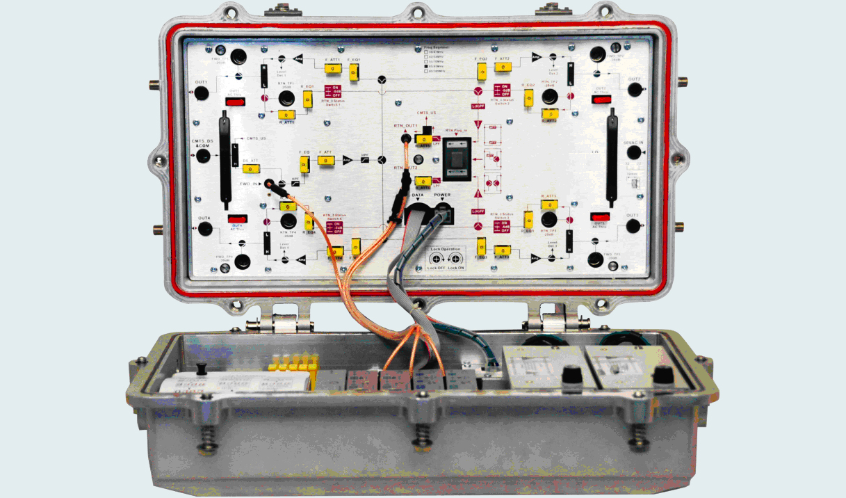
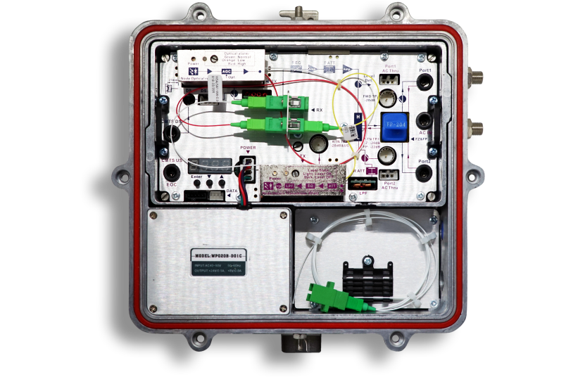
AON2400C Series 4 port Node is part of ACT Deep Fiber solution, which helps operators expand bandwidth of their existing HFC network while minimizing capital investment. The AON2400C 4 port node is designed with four high outputs up to 108dBuV.
• Forward path optical receiving part adopts advanced optical AGC technology, the input optical power range extended to -8 dBm to +2 dBm.
• Forward path optical receiving part: RF operating bandwidth extended to 1 GHz, each way maximum output level up to 114 dBμV.
• The attenuation and equilibrium control circuit adopts fixed inserter, and achieve remote monitoring by NMS.
• RF amplifier part adopts quick plug modular design, can quickly replace RF amplifier module without dismantling the RF cable connector.
• Built-in perfect condition monitoring circuit, and support Ethernet transponder.
• Built-in tri-state gate switch circuit in the return path. Three states passthrough, -6 dB and OFF can be remote set by network management responder.
• Reserved C-CMTS forward path and return path RF interface, support DOCSIS EOC networking scheme.
Item | Description | ||
Forward | |||
Optical Parameters | |||
Optical AGC control range | +2 dBm to ‑8/‑7/‑6/‑5 dBm adjustable | ||
Optical Return Loss | >45 dB | ||
Optical Receiving Wavelength | 1100 nm to 1600 nm | ||
FC/APC, SC/APC or specified by the user | |||
Link Performance | |||
C/N | ≥51 dB | ||
C/CTB | ≥65 dB | ||
C/CSO | ≥60 dB | ||
RF Parameters | |||
Frequency Range | 54/85 MHz to 862/1003 MHz | ||
Flatness in Band | ±0.75 dB | ||
Rated Output Level | ≥108 dBµV (when the optical AGC control range is +2 to ‑8) | ||
Max Output Level | ≥114 dBµV | ||
Output Return Loss | 85 MHz to 550MHz: ≥16 dB 550 MHz to 1000MHz: ≥14 dB | ||
Redundant Receiver Isolation | ≥75 dB | ||
Output Impedance | 75 Ω | ||
Optical Parameters | |||
Optical Transmit Wavelength | 1310 nm ± 10 nm, 1550 nm ± 10 nm, or specified by user | ||
Laser Type | DFB or FP laser | ||
Output Optical Power | 1 mW | ||
Optical Connector Type | FC/APC, SC/APC (or specified by the user) | ||
RF Parameters | |||
Frequency Range | 5 MHz to 42 MHz (or specified by the user) | ||
Flatness in Band | ±0.75 dB | ||
Input Level | 75 dBµV to 85 dBµV | ||
Input Return Loss | ≥16 dB | ||
Independent Transmit Isolation | ≥60 dB | ||
Input Impedance | 75 Ω | ||
NPR dynamic range | ≥15 dB (NPR≥30 dB) Use DFB laser | ≥10 dB (NPR≥30 dB) Use FP laser | |
RF Parameters of C‑CMTS Interface | |||
CMTS_DS forward path insertion port level | 100 dBµV ± 2 dBµV | ||
CMTS_US return path output gain | 0 dB ± 1 dB | Port to CMTS_US OUT | |
≥70 dB | |||
General Performance | |||
Power voltage | A: 150 VAC to 265 VAC B: 35 VAC to 90 VAC OR 110 VAC | ||
10 A | |||
Operating temperature | ‑40 °C to +60 °C | ||
Storage temperature | ‑40 °C to +70 °C | ||
Relative humidity | 0 % to 95 % RH (non‑condensing) | ||
Consumption | ≤42 VA | ||
Dimensions (L × W × H) | 460 mm × 282 mm × 175 mm | ||

AON2200C Optical Node
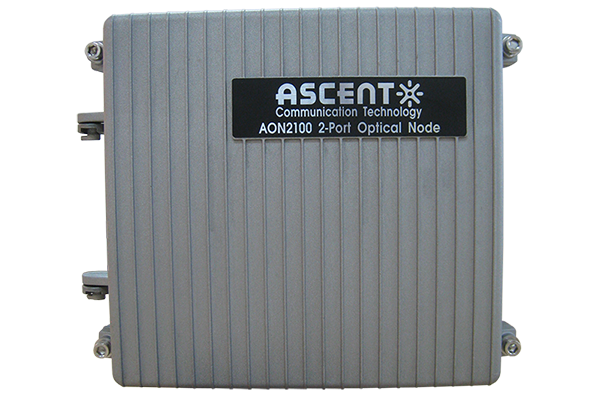
AON2100 Optical Node
AON212X Series Optical Node
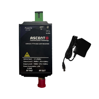
AON121X Series Optical Node
AON1210C Optical Receiver
AON1200D Optical Receiver

AON1110E Optical Receiver

AON1110C Optical Receiver
AON126S Mini Mode
AON121 Mini Node
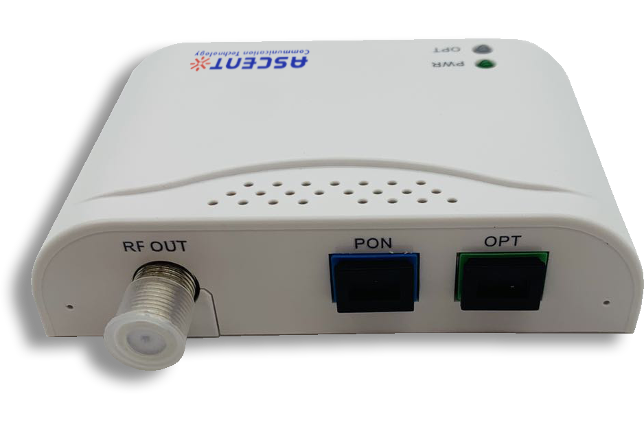
AON120D Mini Node
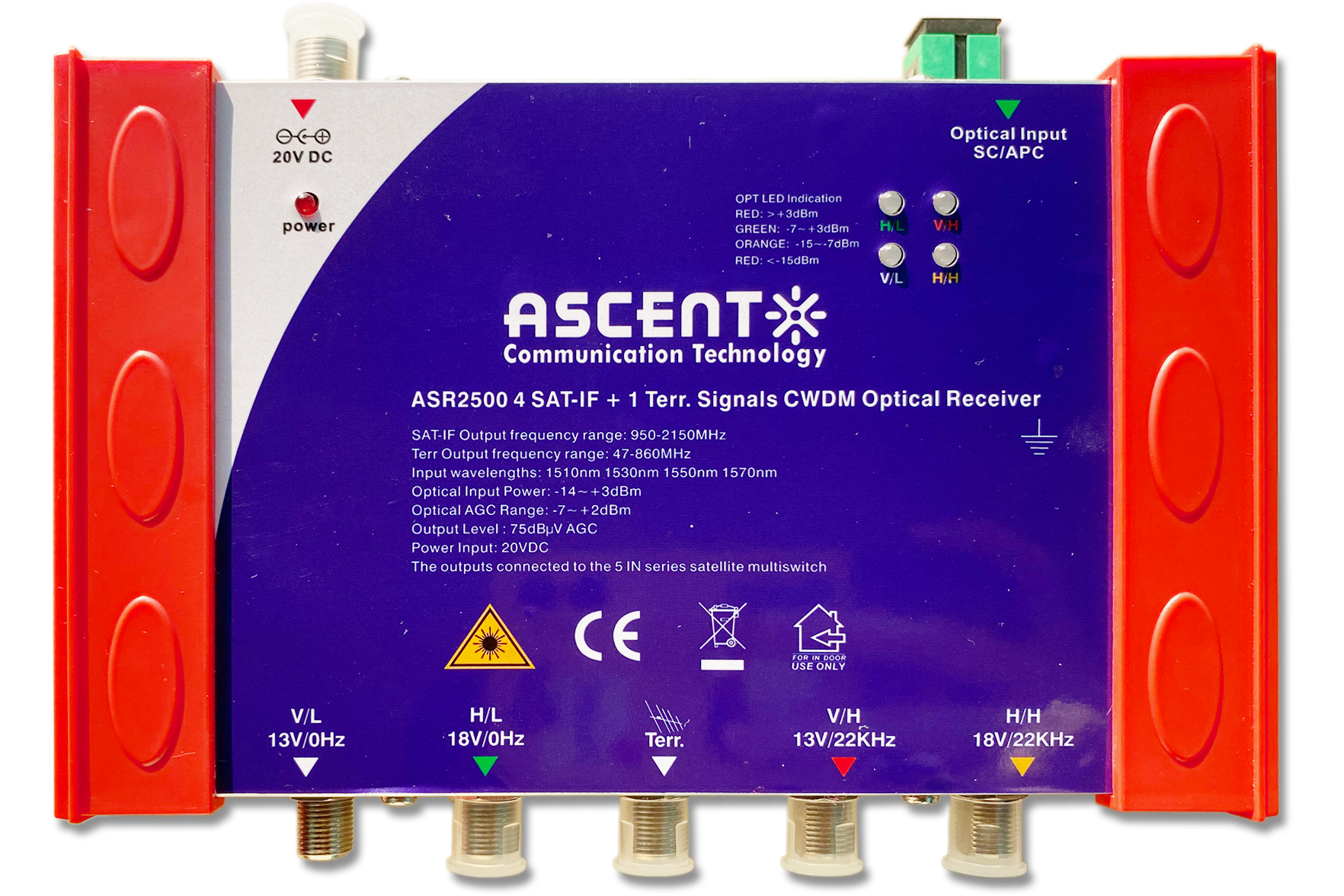
ASR2500 Fiber Satellite CWDM Optical Receiver
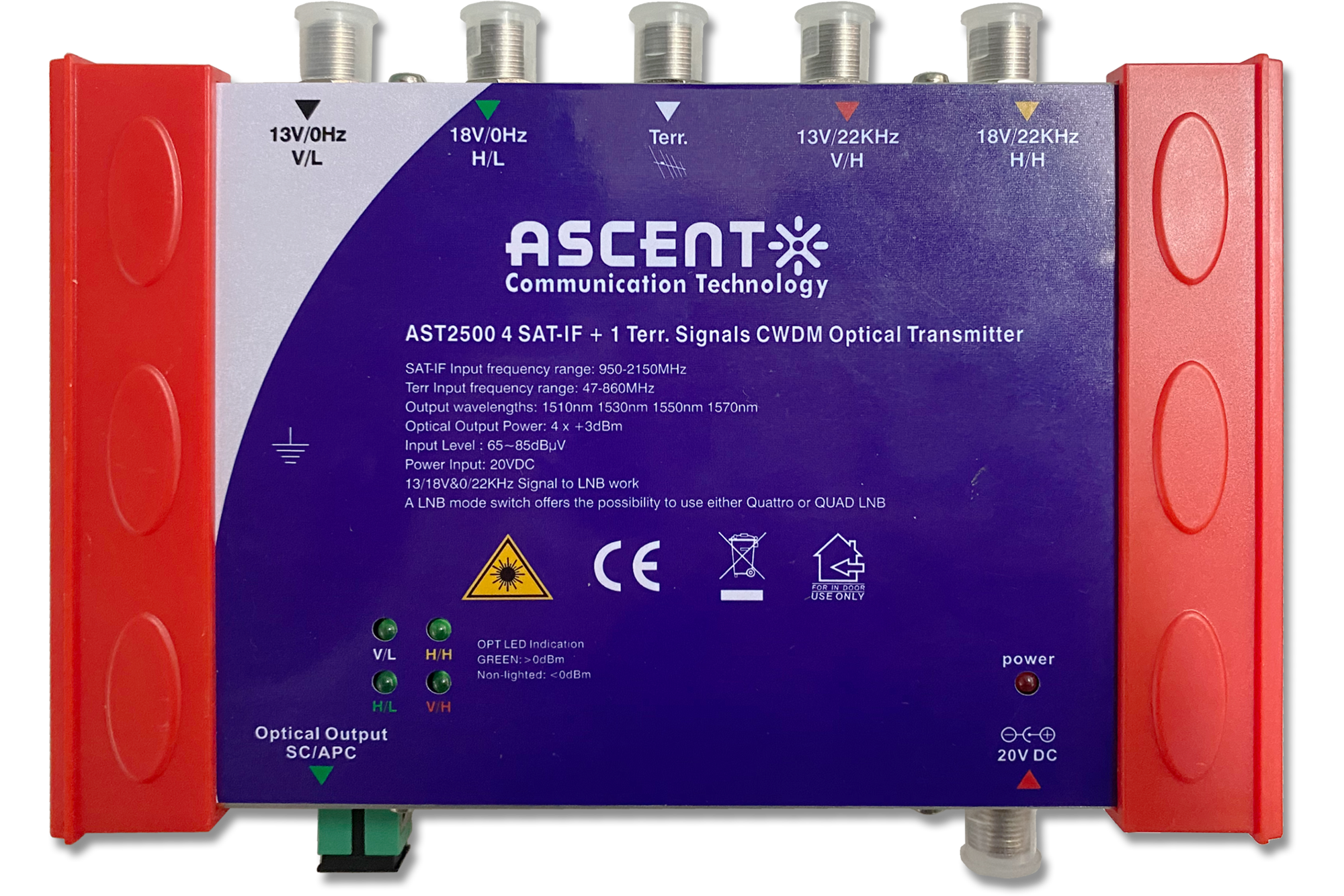
AST2500 Fiber Satellite CWDM Optical Transmitter
