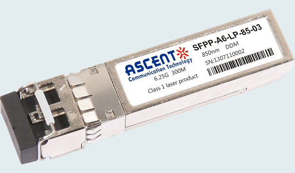
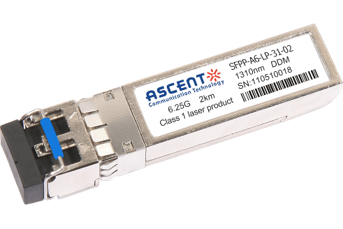
Ascent’s DDM SFP+ transceivers are designed for use in 6.25 Gigabit Ethernet links with distances up to 300 m over multi-mode fiber. These transceivers include a PIN photo detector diode and VSCEL transmitter. Digital diagnostic functions are available via a 2-wire interface.
• Supports up to 6.25 Gb/s bit rates with DDM
• Up to 300 m transmission distance on MMF
• VSCEL transmitter and PIN photo-detector
• Metal enclosure, for lower EMI
• 2-wire interface with integrated digital diagnostic monitoring
• Hot-pluggable SFP+ footprint
• Specifications compliant with SFF 8431 and SFF 8472
• Compliant with SFP+ MSA
• Single 3.3 V power supply
Parameter | Symbol | Min. | Typ. | Max. | Unit | Note |
Maximum Supply Voltage | Vcc | 3.15 | ‑ | 3.46 | V | |
Storage Temperature | TS | ‑40 | ‑ | 85 | °C | |
Case Operating Temperature | Tcase | 0 | ‑ | 70 | °C | Commercial |
‑40 | ‑ | 85 | °C | Industrial |
Electrical Characteristics
Parameter | Symbol | Min. | Typ. | Max. | Unit | Note |
Supply Voltage | Vcc | 3.15 | 3.3 | 3.46 | V | |
Supply Current | Icc | 300 | mA | |||
Transmitter | ||||||
Input Differential Impedance | Rin | 100 | Ω | 1 | ||
Differential Data Input Swing | Vin,pp | 180 | 700 | mV | ||
Transmit Disable Voltage | VDIS | Vcc‑1.3 | Vcc | V | ||
Transmit Enable Voltage | VEN | Vee | Vee+ 0.8 | V | 2 | |
Transmit Disable Assert Time | 10 | us | ||||
Receiver | ||||||
Differential Data Output Swing | Vout,pp | 300 | 850 | mV | 3 | |
Data Output Rise Time | tr | 28 | ps | 4 | ||
Data Output Fall Time | tf | 28 | ps | 4 | ||
LOS Fault | VLOS fault | Vcc‑1.3 | VCCHOST | V | 5 | |
LOS Normal | VLOS norm | Vee | Vee+0.8 | V | 5 |
Notes:
1. Connected directly to TX data input pins. AC coupled thereafter.
2. Or open circuit.
3. Into 100 Ω differential termination.
4. 20 % to 80 %.
5. Loss Of Signal is LVTTL. Logic 0 indicates normal operation; logic 1 indicates no signal detected.
Optical Characteristics
Parameter | Symbol | Min. | Typ. | Max. | Unit | Note |
Transmitter | ||||||
Average Output Power | POUT | ‑6 | ‑1 | dBm | 1 | |
Optical Wavelength | λ | 830 | 860 | nm | ||
Spectral Width (RMS) | σ | 0.85 | nm | |||
Optical Extinction Ratio | ER | 3.5 | dB | |||
RIN | RIN | ‑128 | dB/Hz | |||
Receiver | ||||||
Rx Sensitivity | RSEN | ‑12 | dBm | 2 | ||
Input Saturation Power (Overload) | PSAT | ‑1 | dBm | |||
Input Optical Wavelength | λC | 830 | 860 | nm | ||
LOS De ‑Assert | LOSD | ‑13 | dBm | |||
LOS Assert | LOSA | ‑30 | dBm | |||
LOS Hysteresis | 0.5 | 1.0 | dB |
Notes:
1. Class 1 Laser Safety per FDA/CDRH and IEC‑825‑1 regulations.
2. With worst‑case extinction ratio. Measured with a PRBS 231‑1 test pattern, BER<10‑12.

10G SFP+ LR 1310 nm 40 km

10G SFP+ LR 1310 nm 20 km
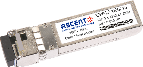
10G SFP+ LR 1310 nm 10 km

10G SFP+ LRM 1310 nm 2 km
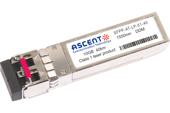
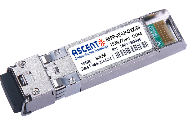
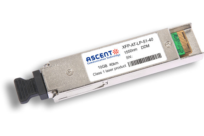
10G SFP+ ER 1550 nm 40 km
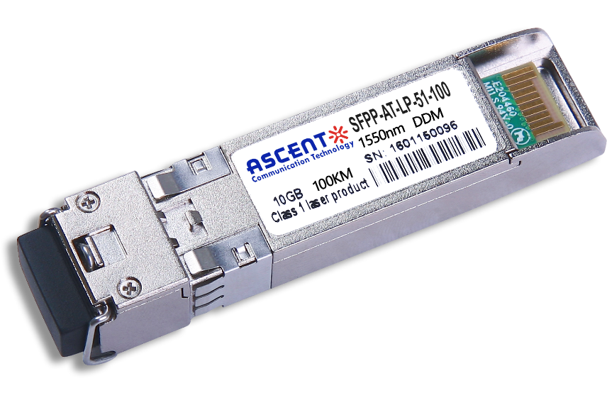
10G SFP+ CDR 1550 nm 100 km
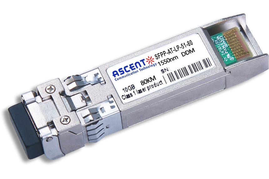
10G SFP+ ZR 1550 nm 80 km
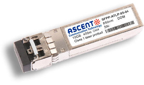
10G SFP+ 850 nm 400 m
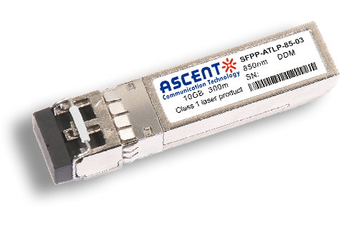
10G SFP+ 850 nm 300 m
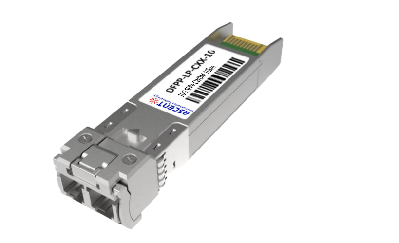
10G SFP+ Tunable DWDM 80 km
10G SFP+ DWDM 80 km
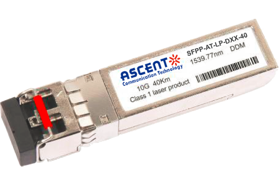
10G SFP+ DWDM 40 km
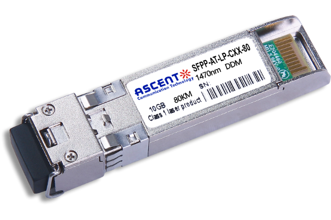
10G SFP+ CWDM 80 km
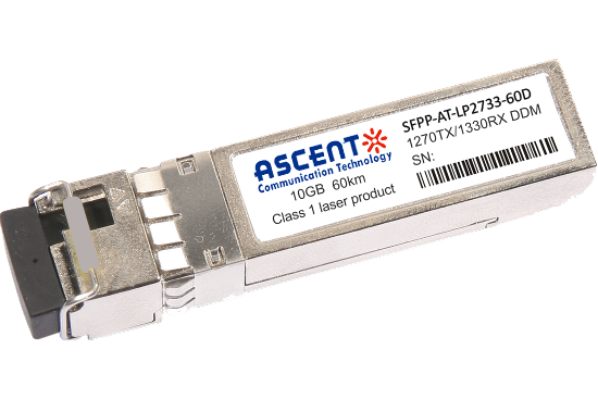
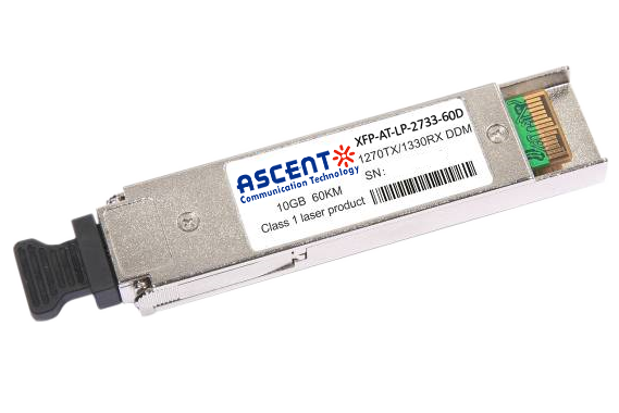
10G SFP+ CWDM 2733 60 km
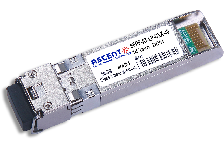
10G SFP+ CWDM 40 km
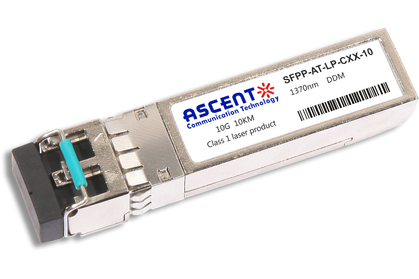
10G SFP+ CWDM 10 km
10G SFP+ Single mode CWDM 10 km
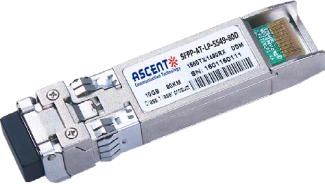
10G SFP+ CWDM 4955 80 km
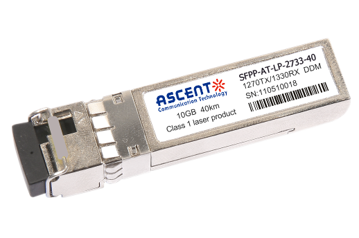
10G SFP+ CWDM 2733 40 km
10G SFP+ CWDM 2733 10 km

10G XFP BIDI 80KM

10G XFP BIDI 40KM

10G XFP BIDI 20KM

10G XFP BIDI 10KM

10G XFP LR 1310 nm 20 km

10G XFP LR 1310 nm 10 km
10G XFP ER 1550 nm 40 km

10G XFP ZR 1550 nm 80 km
10G XFP CWDM 2633 60 km
10G SFP+ CWDM 1610 80 km
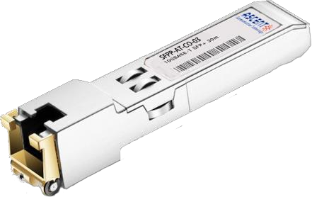
10G SFP+ Copper RJ45 30 m

10G X2 850nm 300m
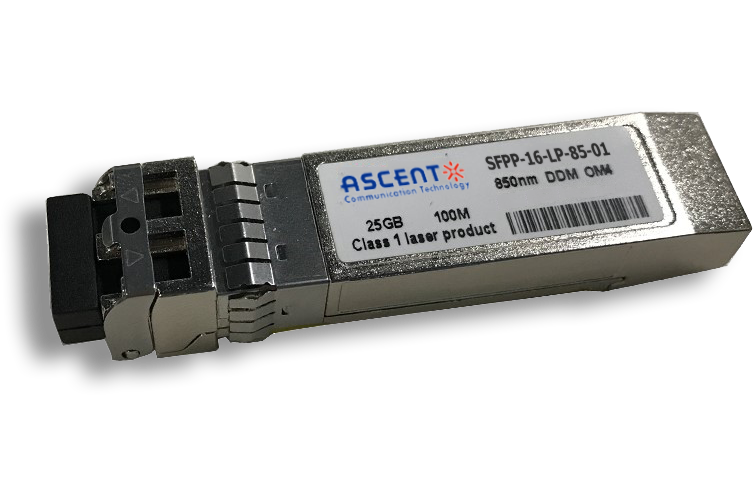
16G SFP+ FC 850 nm 100 m
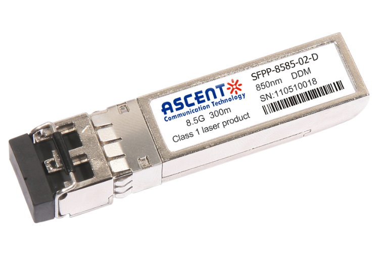
8.5G SFP+ SR 850 nm 150 m
6.25G SFP+ LRM 1330 nm 2 km
