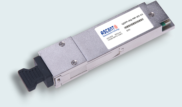
ASCENT’s QSFP+ Series are designed for use in 40 Gigabit per second links over multimode fiber. They are compliant with the QSFP+ MSA and IEEE 802.3ba 40GBASE-SR4.
• High channel capacity: 40 Gbps per module
• Up to 11.1 Gbps data rate per channel
• 100 m links on OM3 multi-mode fiber
• 150 m links on OM4 multi-mode fiber
• High reliability 850 nm VCSEL technology
• Hot-pluggable
• Digital diagnostic SFF-8436 compliant
• Power dissipation < 0.7 W
• ROHS, FCC complaint
Absolute Maximum Ratings
Parameter | Symbol | Min. | Typ. | Max. | Unit | Note |
Storage Temperature | Ts | ‑40 | ‑ | 85 | °C | |
Relative Humidity | RH | 5 | ‑ | 95 | % | |
Power Supply Voltage | VCC | ‑0.3 | ‑ | 4 | V | |
Signal Input Voltage | Vcc‑0.3 | ‑ | Vcc+0.3 | V | ||
Damage threshold | 3.4 | dBm |
Recommended Operating Conditions
Parameter | Symbol | Min. | Typ. | Max. | Unit | Note |
Case Operating Temperature | Tcase | 0 | ‑ | 70 | °C | Without air flow |
Power Supply Voltage | VCC | 3.14 | 3.3 | 3.46 | V | |
Power Supply Current | ICC | ‑ | 200 | mA | ||
Data Rate | BR | 10.3125 | Gbps | Each channel | ||
Transmission Distance | TD | ‑ | 100 | m | OM3 MMF | |
150 | m | OM4 MMF |
Optical Characteristics
Parameter | Symbol | Min | Typ. | Max | Unit | Note |
Transmitter | ||||||
Center Wavelength | λ0 | 840 | 860 | nm | ||
Average Launch Power Each Lane | ‑7.6 | 1.0 | dBm | |||
Spectral Width (RMS) | σ | 0.65 | nm | |||
Optical Extinction Ratio | ER | 3 | dB | |||
Average Launch Power Off Each Lane | Poff | ‑30 | dBm | |||
Transmitter and Dispersion Penalty Each Lane | TDP | 3.5 | dB | |||
Optical Return Loss Tolerance | ORL | 12 | dB | |||
Output Eye Mask | Compliant with IEEE 802.3ba-2010 | |||||
Receiver | ||||||
Receiver Wavelength | λin | 840 | 860 | nm | ||
Rx Sensitivity per Lane | RSENS | ‑11.1 | dBm | 1 | ||
Input Saturation Power (Overload) | Psat | 2.4 | dBm | |||
Receiver Reflectance | Rr | ‑12 | dB | |||
LOS De‑Assert | LOSD | ‑12 | dBm | |||
LOS Assert | LOSA | ‑30 | dBm | |||
LOS Hysteresis | 0.5 | dBm | ||||
Notes:
1. Measured with a PRBS 231‑1 test pattern, @10.325 Gb/s, BER<10‑12.
Electrical Characteristics
Parameter | Symbol | Min | Typ. | Max | Unit | Note |
Supply Voltage | Vcc | 3.14 | 3.3 | 3.46 | V | |
Supply Current | Icc | 200 | mA | |||
Transmitter | ||||||
Input Differential Impedance | Rin | 100 | Ω | 1 | ||
Differential Data Input Swing | Vin, pp | 180 | 1000 | mV | ||
Single‑Ended Input Voltage Tolerance | VinT | ‑0.3 | 4.0 | V | ||
Receiver | ||||||
Differential Data Output Swing | Vout, pp | 300 | 850 | mV | 2 | |
Single‑Ended Output Voltage | ‑0.3 | 4.0 | V |
Notes:
1. Connected directly to TX data input pins. AC coupled thereafter.
2. Into 100 Ω differential termination.


64G SFP56 850nm 100m

40G QSFP+ ER4 Industrial 40 km

40G QSFP+ ER4 40 km

40G QSFP+ LR4 Industrial 10 km

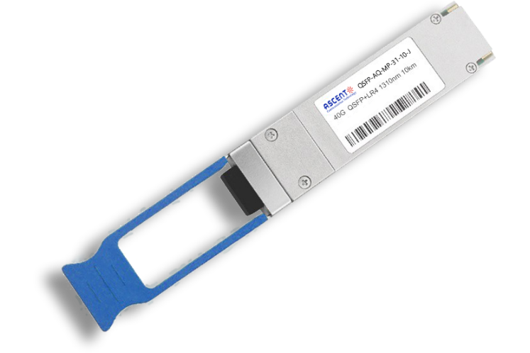
40G QSFP+ LR4 10 km

40G QSFP+ PSM4 2 km
40G QSFP+ PLR4 1310 nm 10 km

40G QSFP+ CSR4 300m
40GBASE-UNIV QSFP+ MMF and SMF
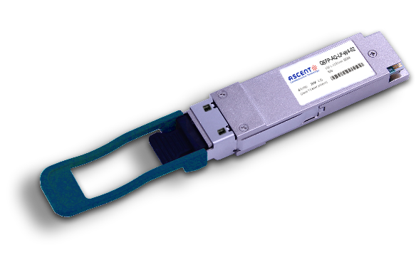
40G QSFP+ CWDM 2 km
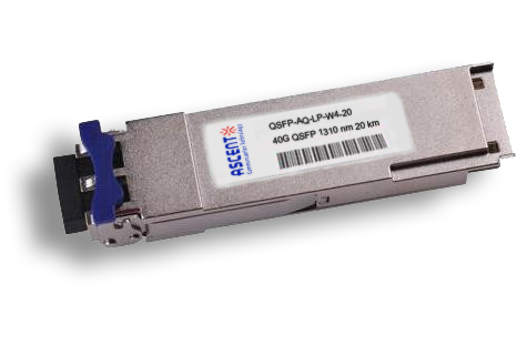
40G QSFP CWDM 20 km
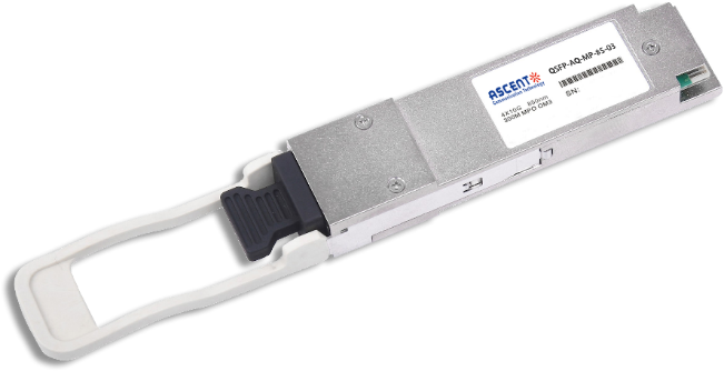
40G QSFP+ SR4 300 m
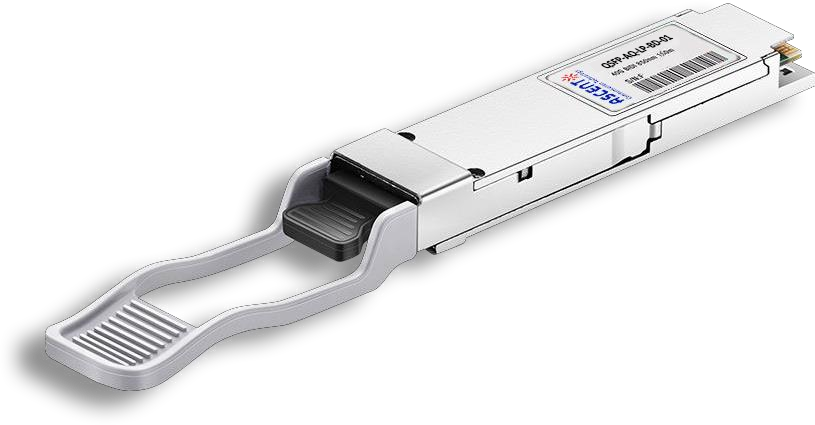
40G QSFP+ BIDI 150m
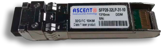
32G SFP28 1310 nm 10 km

32G SFP28 SR 850 nm 100 m
.png)
25G SFP28 CWDM 10 km(E)
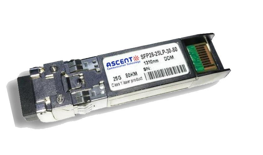
25G SFP28 ZR 1310nm 80km
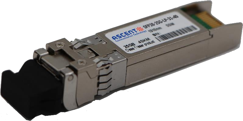
25G SFP28 1310 nm 40km
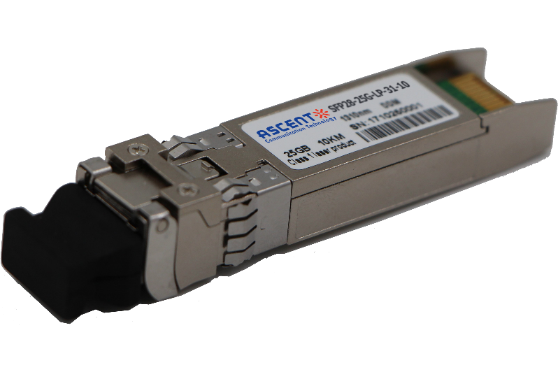
25G SFP28 1310 nm 10 km
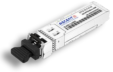
25G SFP28 850 nm 300m
25G SFP28 850 nm 100m

10/25G SFP28 1310nm 40km
10/25G SFP28 1310nm 10km

10/25G SFP28 850 nm 300m

10/25G SFP28 850 nm 100m
