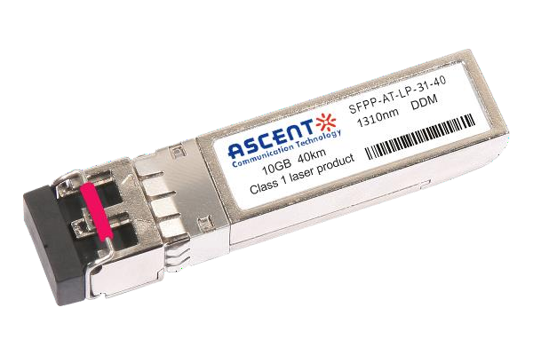
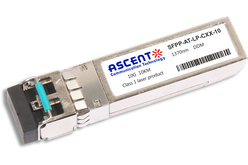
ASCENT’s SFPP-ATLP-31-10 Small Form Factor Pluggable (SFP) transceivers are compatible with the Small Form Factor Pluggable Multi-Sourcing Agreement (MSA). The transceiver consists of five sections: the LD driver, the limiting amplifier, the digital diagnostic monitor, the 1310nm FP laser and the PIN photo-detector. The module data link up to 10 km using 9/125 µm single-mode fiber. The optical output can be disabled by a TTL logic high-level input of Tx Disable, and the system also can disable the module via I2C. Tx Fault is provided to indicate that degradation of the laser. Loss Of signal (LOS) output is provided to indicate the loss of an input optical signal of receiver or the link status with partner. The system can also get the LOS (or Link)/Disable/Fault information via I2C register access.The metal housing ensures low EMI interference standards, with connector retainer.
· Support data rate up to 11.32Gb/s
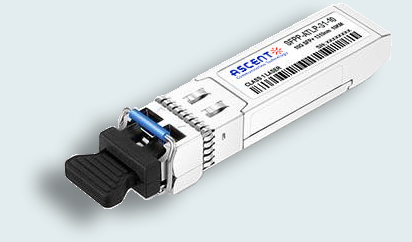
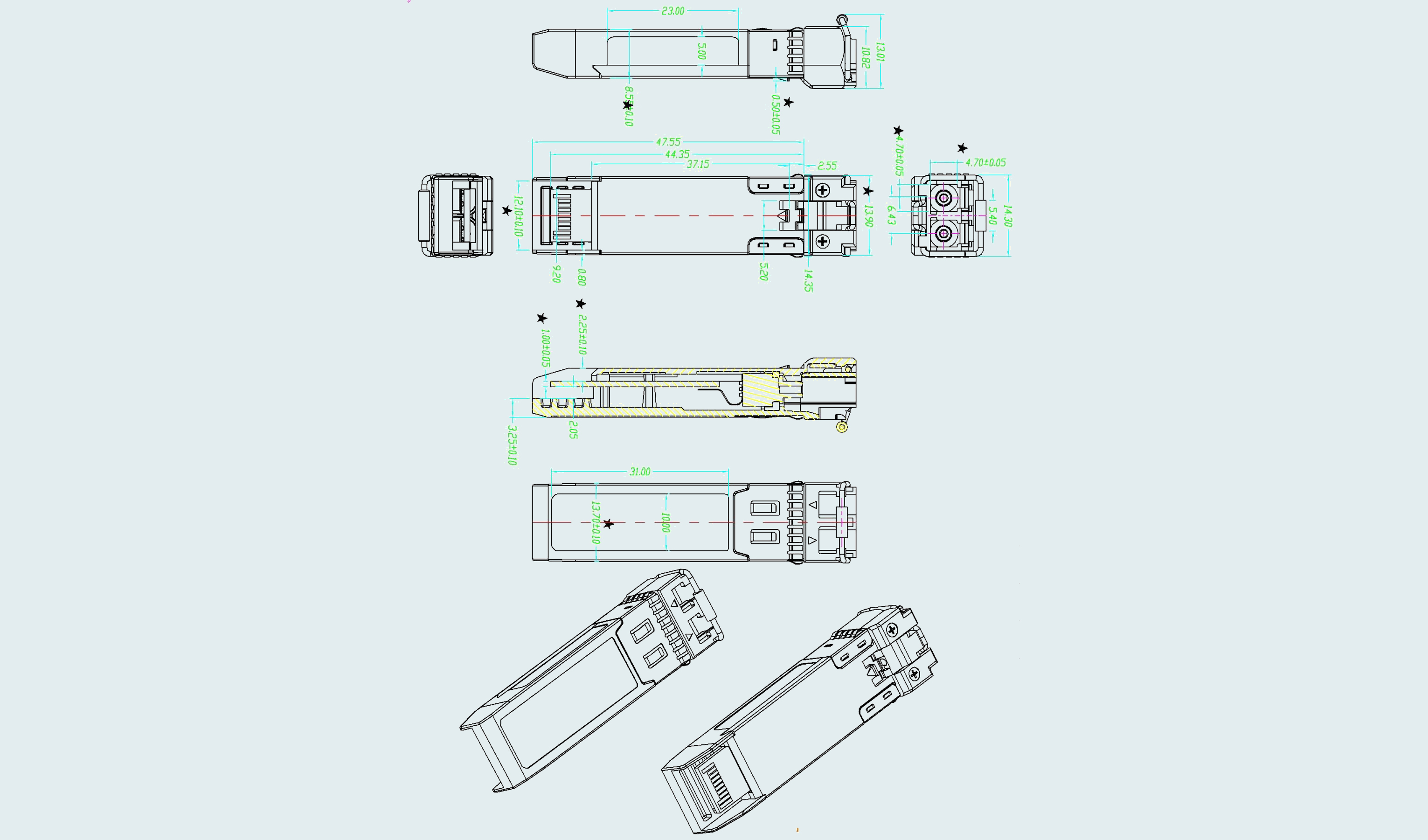
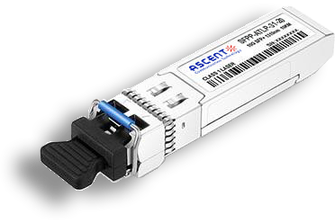
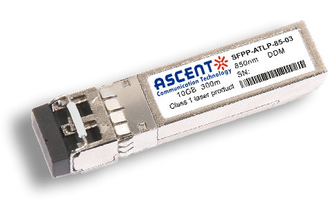
· Hot-Pluggable SFP Footprint and Dual LC Connector
· Up to 10km long range(LR) for G.652 SMF
· 1310nm DFB laser and PIN receiver
· ESD protect
· Low EMI metals
· Temperature Range:
Commercial: 0°C to +70°C
Industrial: -40°C to +85°C
· Compliant with SFP-8431
· Compliant with SFP-8432
· Compliant with SFP-8472
· Compliant with IEEE802.3ae, 10GBase-LR/LW
Absolute Maximum Ratings
Parameter | Symbol | Min. | Typ. | Max. | Unit | Note |
Storage Temperature | TS | -40 | 85 | °C | ||
Maximum Supply Voltage | VCC | -0.5 | 3.6 | V | ||
Operating Relative Humidity | RH | 95 | % |
Recommended Operating Conditions
Parameter | Symbol | Min. | Typ. | Max. | Unit | Note |
Operating Case Temperature | TOP | 70 | °C | Commercial | ||
-40 | - | 85 | Industrial | |||
Power Supply Voltage | VCC | 3.13 | 3.3 | 3.47 | V | |
Data Rate | BR | 1.25 | 10.3125 | Gbps | ||
Transmission Distance | TD | 10 | km | |||
Coupled Fiber | Single-mode fiber | 9/125 µm G.652 | ||||
Parameter | Symbol | Min. | Typ. | Max. | Unit | Note |
Supply Voltage | VCC | 3.1 | 3.5 | V | ||
Supply Current (Commercial) | ICC | 300 | mA | |||
Supply Current (Industrial) | ICC | 360 | mA | |||
Power Consumption (Commercial) | P | 1.0 | W | |||
Power Consumption (Industrial) | P | 1.2 | W | |||
Transmitter Section | ||||||
CML Inputs(Differential) | Vin, pp | 180 | 700 | mV | ||
Input Impedance(Differential) | VDIS | 2 | VCC | V | ||
TX_DIS Disable | 2 | Vcc+0.3 | V | |||
TX_DIS Enable | 0 | 0.8 | V | |||
TX_FAULT Fault | 2 | Vcc+0.3 | V | |||
TX_FAULT Normal | 0 | 0.5 | V | |||
Receiver Section | ||||||
CML Outputs (Differential) | Vout | 350 | 700 | mVpp | 1 | |
Output Impedance (Differential) | Zout | 90 | 100 | 105 | Ohm | |
RX_LOS LOS | 2 | Vcc+0.3 | V | 2 | ||
RX_LOS Normal | 0 | 0.8 | V | 2 | ||
MOD_DEF ( 0:2 ) VoH | 2.5 | V | With Serial ID | |||
MOD_DEF ( 0:2 ) VoL | 0 | 0.5 | V | With Serial ID | ||
1. CML logic, internally AC coupled.
2. Loss of Signal is LVTTL. Logic 0 indicates normal operation; logic 1 indicates no signal detected.
Optical Characteristics
Parameter | Symbol | Min. | Typ. | Max. | Unit | Note |
Data Rate | VCC | 1.25 | 10.3125 | 11.32 | Gbps | |
Transmitter | ||||||
Center Wavelength | λc | 1260 | 1310 | 1355 | nm | |
Spectral Width (-20dB) | ∆λ | 1 | nm | |||
Side Mode Suppression Ratio | SMSR | 30 | dB | |||
Average Output Power | Pout | -8.2 | 0.5 | dBm | ||
Extinction Ratio | ER | 3.5 | dB | |||
Average Power of OFF Transmitter | Poff | -30 | dBm | |||
Relative Intensity Noise | RIN | -128 | dB/Hz | 2 | ||
Receiver | ||||||
Wavelength Range | λC | 1260 | 1620 | nm | ||
Receiver Sensitivity | Pmin | -14.4 | dBm | 3 | ||
Receiver Overload | Pmax | 0.5 | dBm | |||
LOS De-Assert | LOSD | -16 | dBm | |||
LOS Assert | LOSA | -30 | dBm | |||
LOS-Hysteresis | Phys | 0.5 | 5 | dB | ||
Notes:
1. Output is coupled into a 9/125um SMF.
2. 12dB reflection.
3. Measured with worst ER, BER less than 1E-12 and PRBS 2^31-1 at 10.3125 Gbps
Digital Diagnostic Functions
Parameter Case Temperature | Range 0 to +70 | Unit °C | Accuracy ±3°C | Calibration Internal / External |
Industrial Temperature | -30 to +85 | °C | ±3°C | Internal / External |
Voltage | 3.0 to 3.6 | V | ±3% | Internal / External |
Bias Current | 10 to 100 | mA | ±10% | Internal / External |
TX Power | -6 to +0 | dBm | ±3dB | Internal / External |
RX Power | -15 to +0.5 | dBm | ±3dB | Internal / External |
Note:
The transceivers provide serial ID memory contents and diagnostic information about the present operating conditions by the 2-wire serial interface (SCL, SDA).
The diagnostic information with internal calibration or external calibration all are implemented, including received power monitoring, transmitted power monitoring, bias current monitoring, supply voltage monitoring and temperature monitoring.
Timing Characteristics
Parameter | Symbol | Min. | Typical | Max. | Unit |
TX_Disable Assert Time | t_off | 100 | us
| ||
TX_Disable Negate Time | t_on | 2 | ms | ||
Time to Initialize Include Reset of TX_FAULT | t_int | 300 | ms | ||
TX_FAULT from Fault to Assertion | t_fault | 100 | us | ||
TX_Disable Time to Start Reset | t_reset | 10 | us | ||
Receiver Loss of Signal Assert Time | TA,RX_LOS | 100 | us | ||
Receiver Loss of Signal Deassert Time | Td,RX_LOS | 100 | us | ||
Rate-Select Chage Time | t_ratesel | 10 | us | ||
Serial ID Clock Time | t_serial-clock | 100 | kHz |


10G SFP+ LR 1310 nm 40 km
10G SFP+ LR 1310 nm 20 km

10G SFP+ LRM 1310 nm 2 km
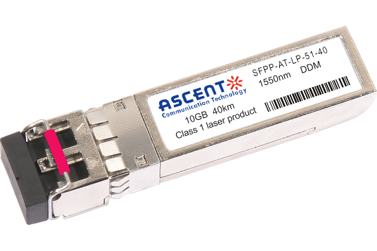
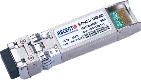
10G SFP+ ER 1550 nm 40 km
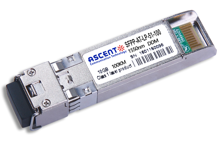
10G SFP+ CDR 1550 nm 100 km
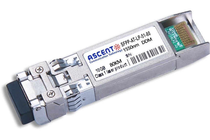
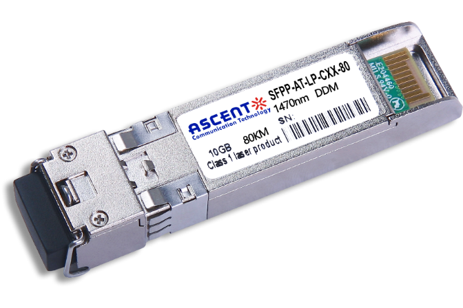
10G SFP+ ZR 1550 nm 80 km
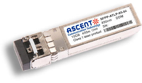
10G SFP+ 850 nm 400 m
10G SFP+ 850 nm 300 m
10G SFP+ Tunable DWDM 80 km
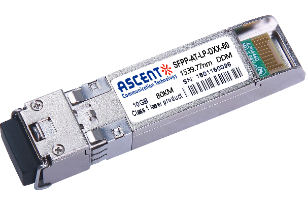
10G SFP+ DWDM 80 km
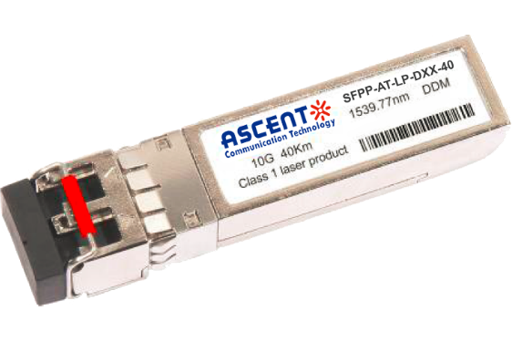
10G SFP+ DWDM 40 km
10G SFP+ CWDM 80 km
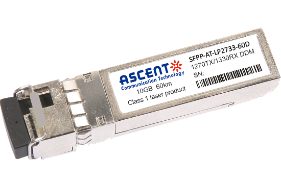
10G SFP+ CWDM 2733 60 km
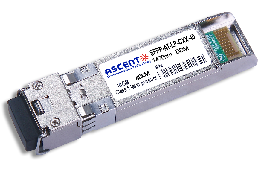
10G SFP+ CWDM 40 km
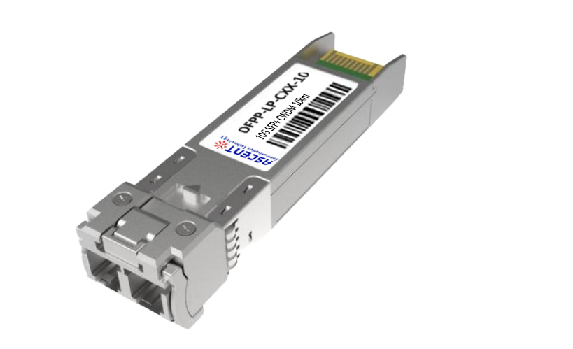
10G SFP+ CWDM 10 km
10G SFP+ Single mode CWDM 10 km
10G SFP+ CWDM 4955 80 km
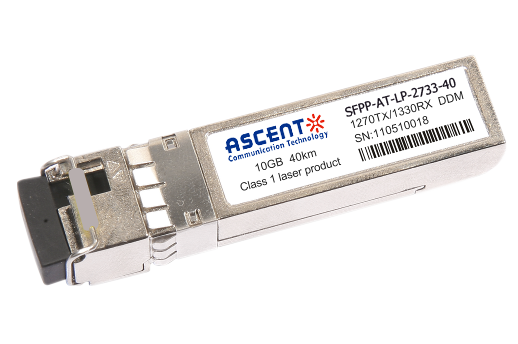
10G SFP+ CWDM 2733 40 km
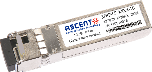
10G SFP+ CWDM 2733 10 km

10G XFP BIDI 80KM

10G XFP BIDI 40KM

10G XFP BIDI 20KM

10G XFP BIDI 10KM

10G XFP LR 1310 nm 20 km

10G XFP LR 1310 nm 10 km
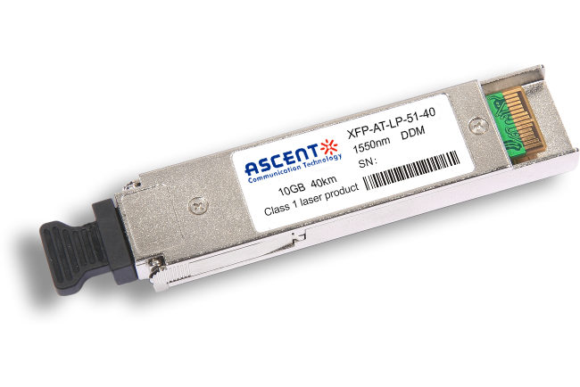
10G XFP ER 1550 nm 40 km

10G XFP ZR 1550 nm 80 km
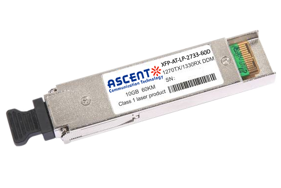
10G XFP CWDM 2633 60 km
10G SFP+ CWDM 1610 80 km
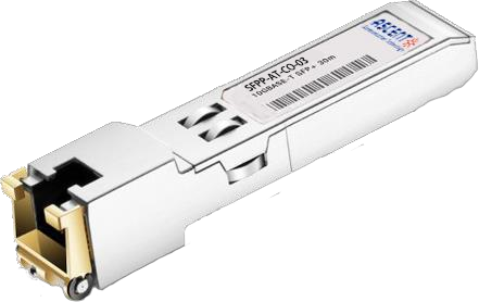
10G SFP+ Copper RJ45 30 m

10G X2 850nm 300m
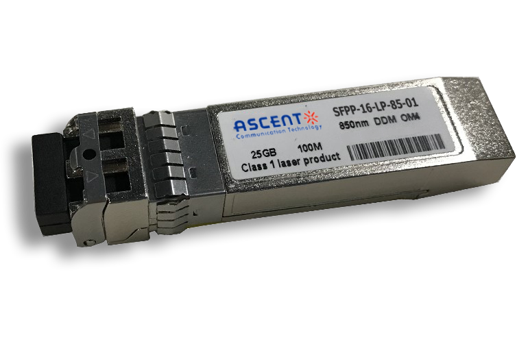
16G SFP+ FC 850 nm 100 m
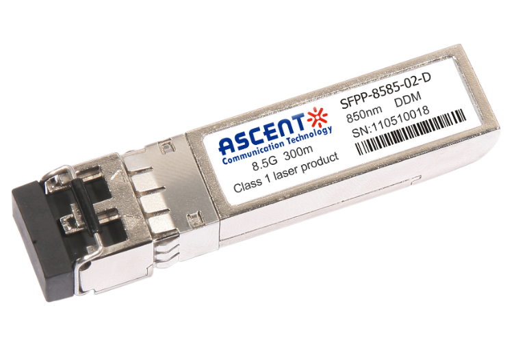
8.5G SFP+ SR 850 nm 150 m
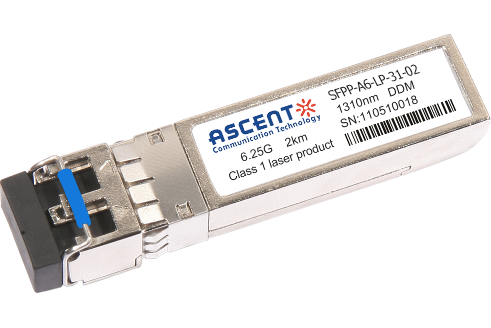
6.25G SFP+ LRM 1330 nm 2 km
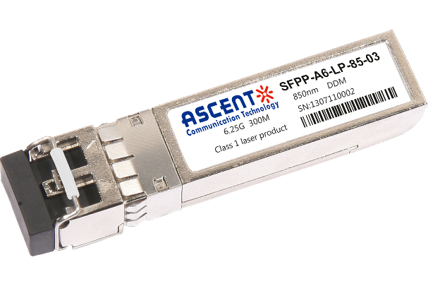
6.25G SFP+ SR 850 nm 300 m
