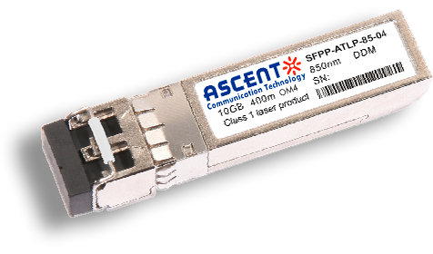
ASCENT SFPP-ATLP-85-04 transceivers support the 2-wire serial communication protocol as defined in the SFP+ MSA, 400m on MMF OM4. SFP+ transceivers provide a unique enhanced digital diagnostic monitoring interface, which allows real-time access to device operating parameters such as transceiver temperature, laser bias current, transmitted optical power, receiver optical power and transceiver supply voltage. It also defines a sophisticated system of alarm and warning flags, which alerts end-users when particular operating parameters are outside of a factory set normal range. The SFP+ MSA defines a 256-byte memory map in EEPROM that is accessible over a 2-wire serialinterface at the 8-bit address 1010000X (A0h). The digital diagnostic monitoring interface makes use of the 8-bit address 1010001X (A2h), so the originally defined serial ID memory map remains unchanged. The operating and diagnostics information is monitored and reported by a Digital Diagnostics Transceiver Controller (DDM) inside the transceiver, which is accessed through a 2-wire serial interface.
· Support multi-protocol from 8.5Gb/s to 11.3Gb/s
· Hot-Pluggable SFP+ footprint
· 850nm VCSEL Tocan laser transmitter
· Duplex LC connector
· Up to 300m links on MMF OM3, 400m on MMF OM4
· Single +3.3V Power Supply
· Power consumption<1W
· Compliant with SFF-8431 SFF-8432 and IEE802.3ae
· Operating temperature range:
Commercial: 0°C to +70°C
Industrial: -40°C to +85°C
· RoHS compliant (lead-free)
Parameter | Symbol | Min. | Typ. | Max. | Unit | Note |
Storage Temperature | TS | -40 | +85 | °C | ||
Case Operating Temperature | TA | 0 | 70 | °C | ||
Supply Voltage | VCC | -0.5 | 3.6 | V | ||
Industrial | TC | -40 | +85 | °C | ||
Commercial | TC | 0 | 70 | °C |
Parameter | Symbol | Min. | Typ. | Max. | Unit | Note |
Bit Rate | BR | 9.95 | 10.3125 | 11.3 | Gb/s | Bit Rate |
Bit Error Ratio | BER | 0 | 10-12 | Bit Error Ratio | ||
Supply Voltage | VCC | -0.5 | 3.6 | V | Supply Voltage | |
Maximum Supported Distances(OM4) | 400 | m | Maximum Supported Distances(OM4) |
Parameter | Symbol | Min. | Typ. | Max. | Unit | Note |
TX_Disable Assert Time | t_off | 10 | us | |||
TX_Disable Negate Time | t_on | 1 | ms | |||
Time to Initialize Include Reset of TX_FAULT | t_int | 300 | ms | |||
TX_FAULT from Fault to Assertion | t_fault | 100 | us | |||
TX_Disable Time to Start Reset | t_reset | 10 | us | |||
Receiver Loss of Signal Assert Time | TA,RX_LOS | 100 | us | |||
Receiver Loss of Signal Deassert Time | Td,RX_LOS | 100 | us | |||
Rate-Select Charge Time | t_ratesel | 10 | us |
Parameter | Symbol | Min. | Typ. | Max. | Unit | Note |
Supply Voltage | Vcc | 3.14 | 3.47 | V | ||
Supply Current | Icc | 300 | mA | |||
Transmitter | ||||||
Input Differential Impedance | Rin | 100 | Ω | 1 | ||
Tx Input Single Ended DC Voltage Tolerance (RefVeeT) | V | -0.3 | 4 | V | ||
Differential Input Voltage Swing | Vin,pp | 100 | 1000 | mV | 2 | |
Transmit Disable Voltage | VD | 2 | Vcc | V | 3 | |
Transmit Enable Voltage | VEN | Vee | +0.8 | V | ||
Receiver | ||||||
Single Ended Output Voltage Tolerance | V | -0.3 | 4 | V | ||
Rx Output Diff Voltage | Vo | 300 | 1000 | mV | ||
Rx Output Rise and Fall Time | Tr/Tf | 30 | ps | 4 | ||
LOS Fault | VLOS fault | 2 | VccHOST | V | 5 | |
LOS Normal | VLOS norm | Vee | +0.8 | V | 5 |
Notes:
1. Connected directly to TX data input pins. AC coupling from pins into laser driver IC.
2. Per SFF-8431 Rev 3.0
3. Into 100 ohms differential termination.
4. 20% to 80%
5. LOS is an open collector output. Should be pulled up with 4.7k – 10kΩ on the host board. Normal operation is logic 0; loss of signal is logic 1. Maximum pull-up voltage is 5.5V.
Optical Characteristics
Parameter | Symbol | Min. | Typ. | Max. | Unit | Note |
Transmitter | ||||||
Center Wavelength | λt | 830 | 850 | 870 | nm | |
RMS Spectral Width | △λrms | 0.45 | nm | |||
Average Optical Power | Pavg | -6 | -1 | dBm | 1 | |
Optical Power OMA | Poma | -1.5 | dBm | |||
Laser Off Power | Poff | -30 | dBm | |||
Extinction Ratio | ER | 3.5 | dB | |||
Transmitter Dispersion Penalty | TDP | 3.9 | dB | 2 | ||
Relative Intensity Noise | Rin | -128 | dB/Hz | 3 | ||
Optical Return Loss Tolerance | 20 | dB | ||||
Receiver | ||||||
Center Wavelength | λr | 830 | 870 | nm | ||
Receiver Sensitivity (OMA) @10.3Gb/s | Sen | -10.5 | dBm | 4 | ||
Stressed Sensitivity (OMA) | SenST | dBm | 4 | |||
Los Assert | LOSA | -25 | dBm | |||
Los De-Assert | LOSD | -12 | dBm | |||
Los Hysteresis | LOSH | 0.5 | dB | |||
Overload | Sat | -1 | dBm | 5 |
Notes:
1. Average power figures are informative only, per IEEE802.3ae.
2. TWDP figure requires the host board to be SFF-8431compliant. TWDP is calculated using the Matlab code provided in clause 68.6.6.2 of IEEE802.3ae.
3. 12dB reflection.
4. Conditions of stressed receiver tests per IEEE802.3ae. CSRS testing requires the host board to be SFF-8431 compliant.
5. Receiver overload specified in OMA and under the worst comprehensive stressed condition.


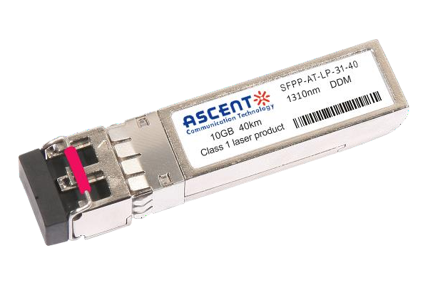
10G SFP+ LR 1310 nm 40 km

10G SFP+ LR 1310 nm 20 km
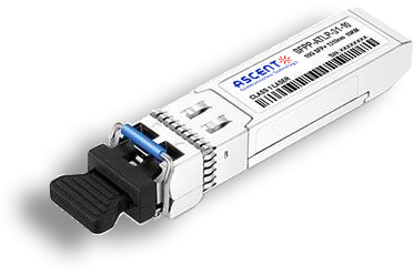
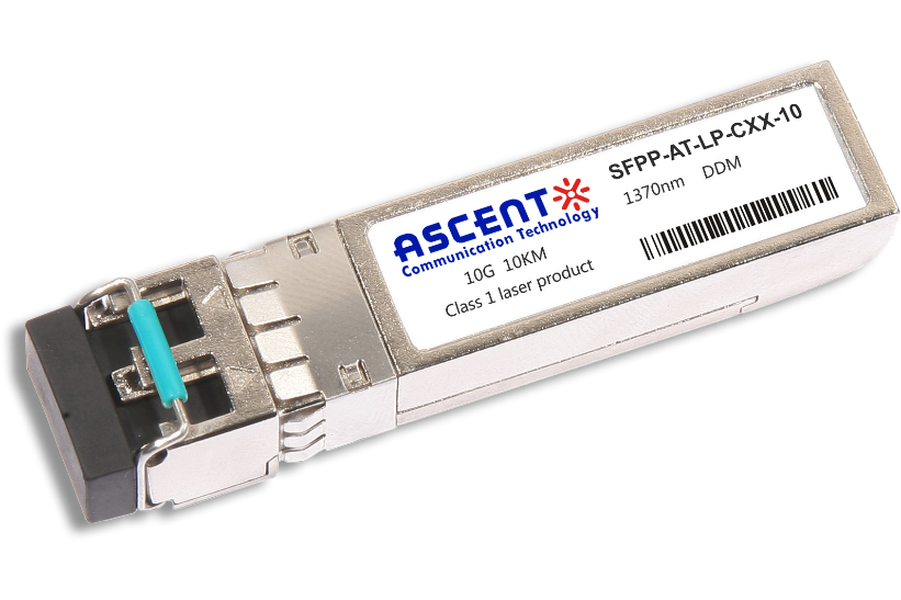
10G SFP+ LR 1310 nm 10 km

10G SFP+ LRM 1310 nm 2 km
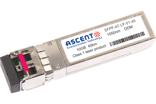
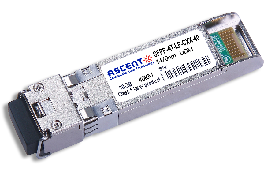
10G SFP+ ER 1550 nm 40 km
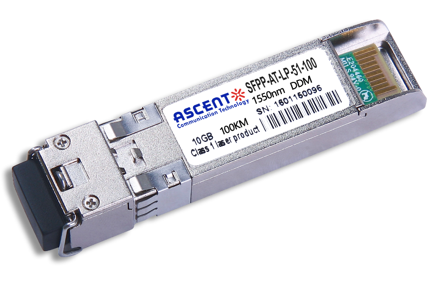
10G SFP+ CDR 1550 nm 100 km
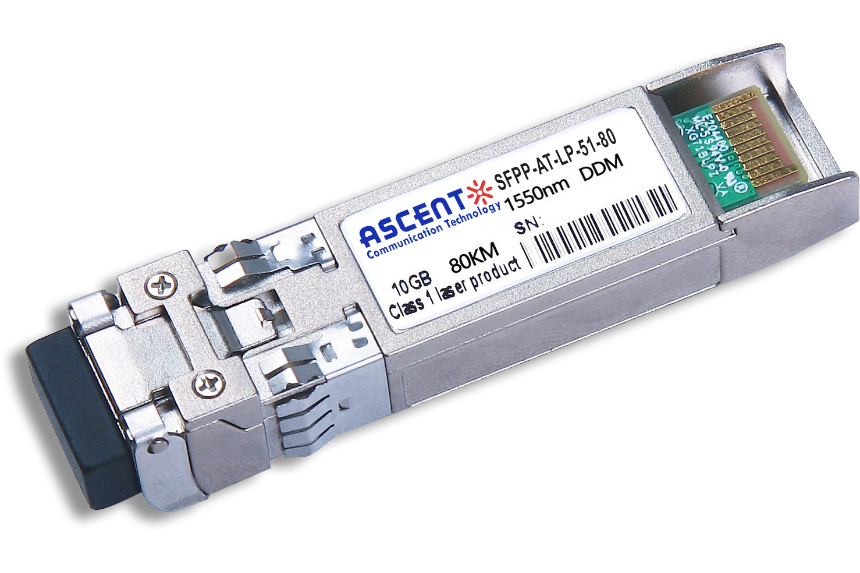
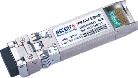
10G SFP+ ZR 1550 nm 80 km
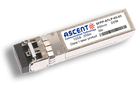
10G SFP+ 850 nm 300 m
10G SFP+ Tunable DWDM 80 km
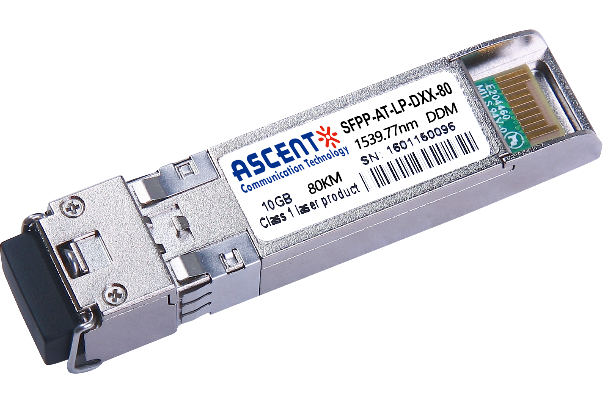
10G SFP+ DWDM 80 km
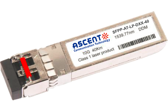
10G SFP+ DWDM 40 km
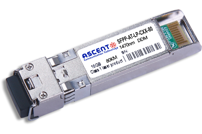
10G SFP+ CWDM 80 km
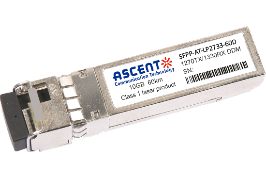
10G SFP+ CWDM 2733 60 km
10G SFP+ CWDM 40 km
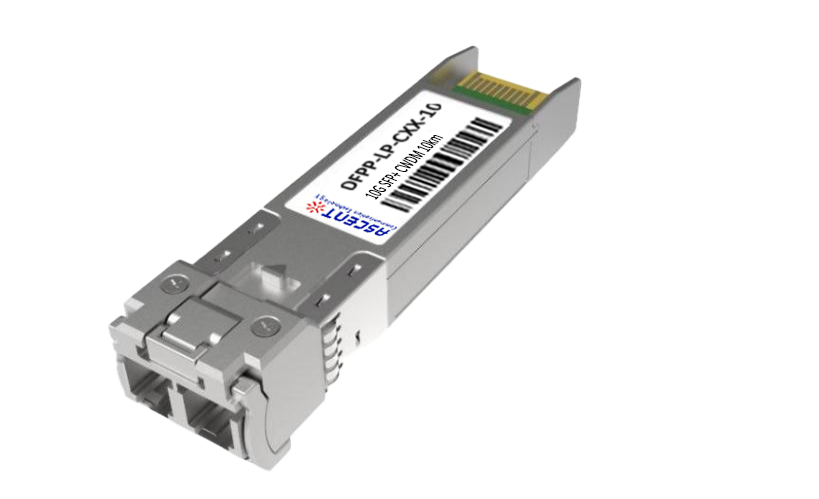
10G SFP+ CWDM 10 km
10G SFP+ Single mode CWDM 10 km
10G SFP+ CWDM 4955 80 km
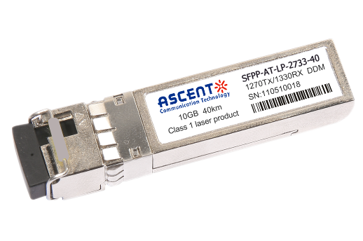
10G SFP+ CWDM 2733 40 km
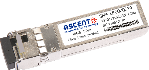
10G SFP+ CWDM 2733 10 km

10G XFP BIDI 80KM

10G XFP BIDI 40KM

10G XFP BIDI 20KM

10G XFP BIDI 10KM

10G XFP LR 1310 nm 20 km

10G XFP LR 1310 nm 10 km
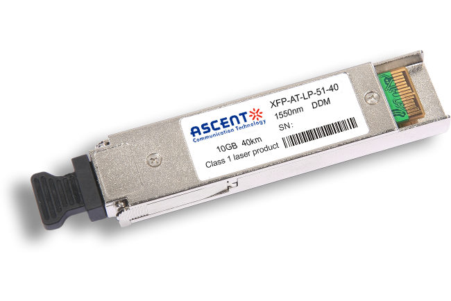
10G XFP ER 1550 nm 40 km

10G XFP ZR 1550 nm 80 km
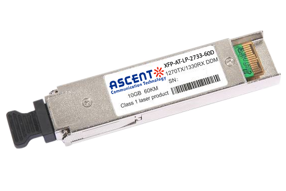
10G XFP CWDM 2633 60 km
10G SFP+ CWDM 1610 80 km
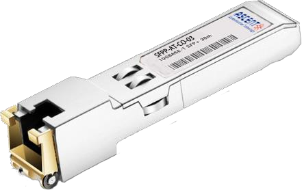
10G SFP+ Copper RJ45 30 m

10G X2 850nm 300m
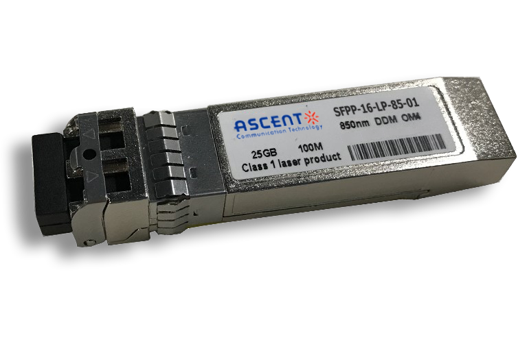
16G SFP+ FC 850 nm 100 m
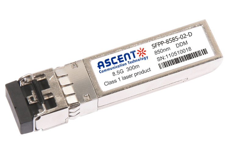
8.5G SFP+ SR 850 nm 150 m
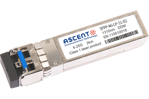
6.25G SFP+ LRM 1330 nm 2 km
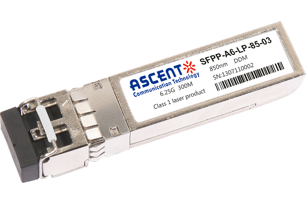
6.25G SFP+ SR 850 nm 300 m
