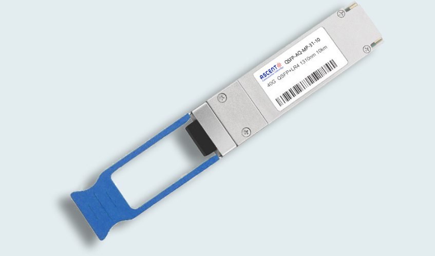
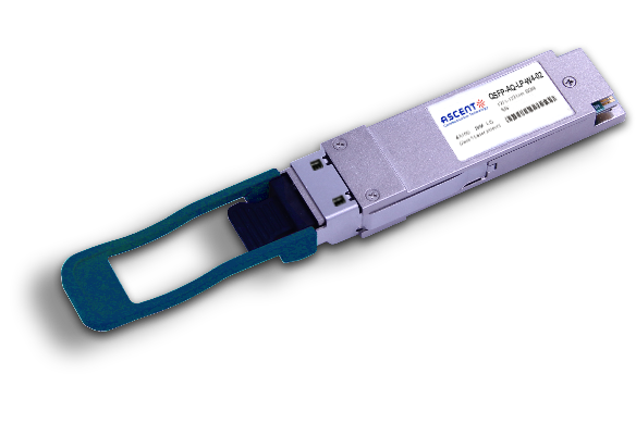
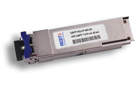
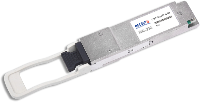
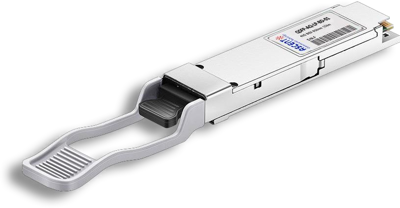
Ascent’s QSFP-AQ-MP-31-10 is a four-channel, hot-pluggable, parallel, fiber-optic QSFP+ transceiver for InfiniBand QDR/DDR/SDR, 10G/8G/4G/2G fiber channel and SAS applications. It is compliant with the QSFP+ MSA, IEEE 802.3ae 10GBASE-LR/LW, and OTN data rates OTU2, OTU1e, and OTU2e per the ITU and designed for use in high density 10 Gigabit Ethernet links over single mode fiber.
• Four-channel full-duplex transceiver modules
• Transmission data rate up to 11.2 Gbit/s per channel
• Up to 10 km transmission distance with single-mode fiber
• DFB laser array inside
• <2.5 W power consumption
• Operating case temperature: 0°C to +70°C
• 3.3 V power supply voltage
• RoHS 6 compliant
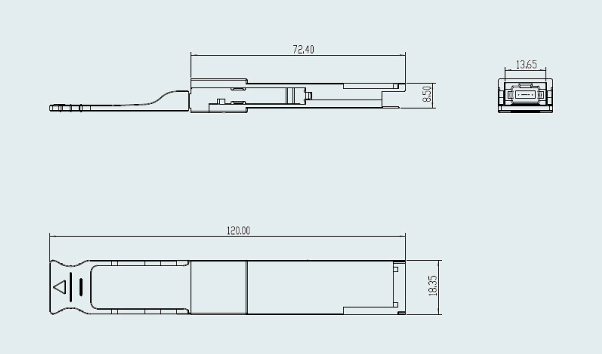
• Hot-pluggable QSFP form factor
• Single MPO connector receptacle
• Built-in digital diagnostic function
Absolute Maximum Ratings
Parameter | Symbol | Min. | Typ. | Max. | Unit | Notes |
Supply Voltage | VCC | ‑0.3 | 3.6 | V | ||
Storage Temperature | TS | ‑40 | 85 | °C | ||
Relative Humidity | RH | 0 | 85 | % | ||
Damage Threshold, per Lane | DT | 3.4 | dBm |
Note: Stress in excess of the maximum absolute ratings can cause permanent damage to the transceiver.
General Operating Characteristics
Parameter | Symbol | Min | Typ. | Max | Units | Notes |
Bit Rate per Lane | BR | 10.313 | Gb/s | 1 | ||
Bit Error Ratio | BER | 10‑12 | 2 | |||
Distance on SMF | D1 | 10 | km | 3 |
Notes:
1. Compliant with 40G Ethernet. Compatible with 1/10 Gigabit Ethernet and 1/2/4/8/10G Fiber Channel.
2. Tested with a PRBS 231‑1 test pattern.
3. Per 40GBASE‑LR4, IEEE 802.3ba.
Optical Characteristics (TOP(C) = 0 °C to +70 °C, VCC = 3.13 V to 3.47 V)
Parameter | Symbol | Min. | Typ. | Max. | Unit | Notes |
Transmitter | ||||||
Operating Wavelength | λC | 1270 | 1310 | 1350 | nm | |
Average Output Power | PAVE | ‑5.2 | +1 | dBm | ||
Difference in Launch Power between any Two Lanes (OMA) | DL | 5 | dB | |||
Extinction Ratio | ER | 3.5 | dB | |||
Peak Power, each Lane | PP | 4 | dBm | |||
Dispersion Penalty, each Lane | TDP | 3.5 | dB | |||
Average Launch Power of OFF Transmitter, each Lane | POFF | ‑30 | dB | |||
Eye Mask Coordinates: X1, X2, X3, Y1, Y2, Y3 | Specification values 0.23, 0.34, 0.43, 0.27, 0.35, 0.4 | 1 | ||||
Receiver | ||||||
Operating Wavelength | λC | 1270 | 1350 | nm | ||
Stressed Receiver Sensitivity in OMA | PSEN1 | ‑12.5 | dBm | 2 | ||
Average Receive Power, each Lane | PAVE | ‑11 | +2.4 | dBm | ||
Receiver Reflectance | Rrx | ‑12 | dB | |||
LOS Assert | Pa | ‑30 | dBm | |||
LOS De‑Assert | Pd | ‑15 | dBm | |||
LOS Hysteresis | Pd‑Pa | 0.5 | dB | |||
Notes:
1. Hit ratio = 5 x 10‑5
2. Measured with conformance test signal at TP3 for BER = 10‑12 Receiver Characteristics

64G SFP56 850nm 100m
40/100G SFP28 SWDM4 100m

40G QSFP+ ER4 Industrial 40 km

40G QSFP+ ER4 40 km

40G QSFP+ LR4 Industrial 10 km

40G QSFP+ LR4 10 km

40G QSFP+ PSM4 2 km

40G QSFP+ CSR4 300m
40GBASE-UNIV QSFP+ MMF and SMF
40G QSFP+ CWDM 2 km
40G QSFP CWDM 20 km
40G QSFP+ SR4 300 m
40G QSFP+ BIDI 150m
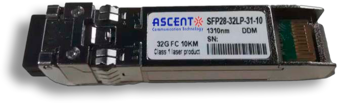
32G SFP28 1310 nm 10 km

32G SFP28 SR 850 nm 100 m
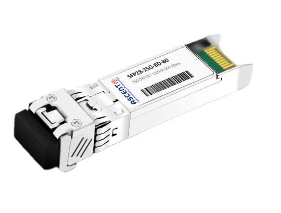
25G SFP28 BIDI 80 km
.png)
25G SFP28 CWDM 10 km(E)
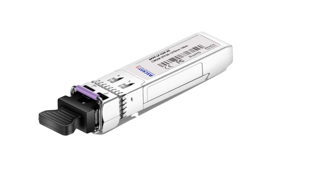
25G SFP28 CWDM 10 km(D)
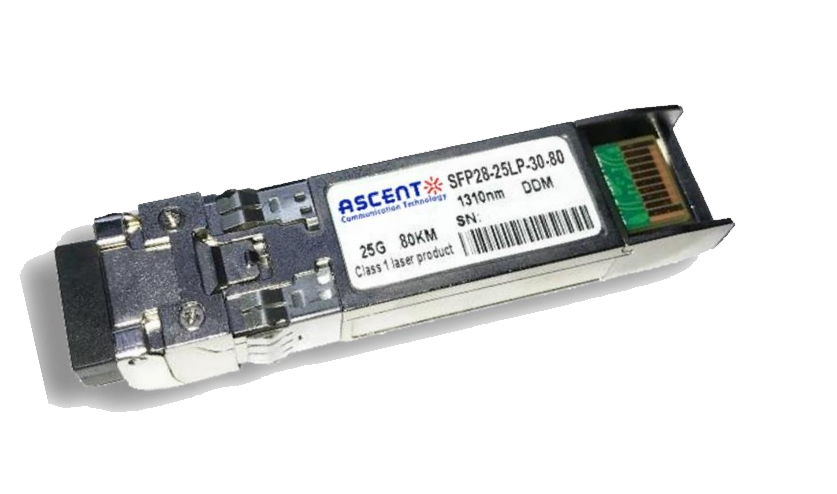
25G SFP28 ZR 1310nm 80km
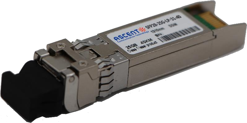
25G SFP28 1310 nm 40km
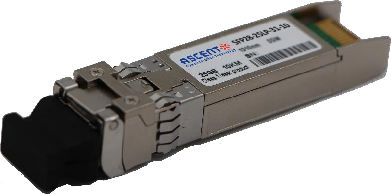
25G SFP28 1310 nm 10 km
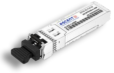
25G SFP28 850 nm 300m

10/25G SFP28 1310nm 40km
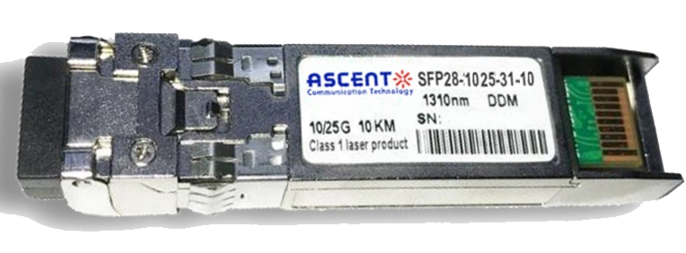
10/25G SFP28 1310nm 10km

10/25G SFP28 850 nm 300m

10/25G SFP28 850 nm 100m
