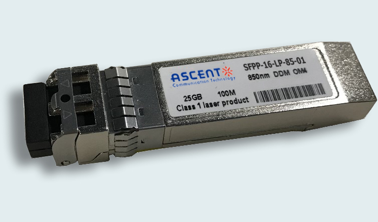
Ascent’s SFPP-16-LP-85-01 SFP+ transceiver is an integrated fiber optic transceiver that provides a high-speed serial link at signaling rates up to 16 Gb/s.
• Up to 14.025 Gbps Data Link
• Maximum link length of 100 m links on OM3 or
• 150 m links on OM4 multi-mode fiber
• Power dissipation < 1W
• VSCEL laser and PIN receiver
• Metal enclosure, for lower EMI
• 2-wire interface with integrated Digital Diagnostic monitoring
• Hot-pluggable SFP+ footprint
• Specifications compliant with SFF 8472
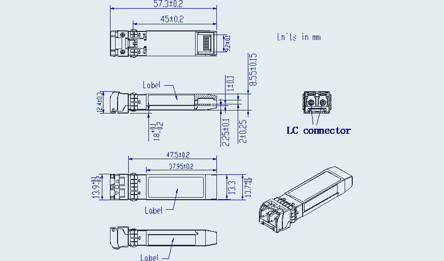
• Compliant with SFP+ MSA with LC connector
• Single 3.3V power supply
• Case operating temperature range: Commercial: 0 °C to +70 °C
Absolute Maximum Ratings
Parameter | Symbol | Min. | Typ. | Max. | Unit | Notes |
Storage Temperature | Ts | ‑40 | ‑ | 85 | °C | |
Relative Humidity | RH | 5 | ‑ | 95 | % | |
Power Supply Voltage | VCC | ‑0.3 | ‑ | 4 | V | |
Signal Input Voltage | Vcc‑0.3 | ‑ | Vcc+0.3 | V |
Recommended Operating Conditions
Parameter | Symbol | Min. | Typ. | Max. | Unit | Note |
Case Operating Temperature | Tcase | 0 | ‑ | 70 | °C | Commercial |
Power Supply Voltage | VCC | 3.14 | 3.3 | 3.47 | V | |
Power Supply Current | ICC | ‑ | 300 | mA | ||
Data Rate | BR | 14.025 | Gbps | |||
Transmission Distance | TD | ‑ | 150 | m | OM4 or 100m OM3 | |
Coupled Fiber | Multi‑mode fiber | 50/125um OM4 | ||||
Optical Characteristics
Parameter | Symbol | Min. | Typ. | Max. | Unit | Notes |
Transmitter | ||||||
Output Opt. Power | POUT | ‑7.8 | 2.4 | dBm | 1 | |
Optical Wavelength | λ | 840 | 850 | 860 | nm | |
Spectral Width (RMS) | σ | 0.6 | nm | |||
Optical Extinction Ratio | ER | 3.0 | dB | |||
RIN | RIN | ‑128 | dB/Hz | |||
Receiver | ||||||
Rx Sensitivity | RSENS | ‑10.5 | dBm | 2 | ||
Input Saturation Power (Overload) | Psat | 0 | dBm | |||
Wavelength Range | λC | 770 | 850 | 860 | nm | |
LOS De ‑Assert | LOSD | ‑13 | dBm | |||
LOS Assert | LOSA | ‑30 | dBm | |||
LOS Hysteresis | 0.5 | dB |
Notes:
1. Class 1 Laser Safety per FDA/CDRH and IEC‑825‑1 regulations.
2. Measured with a PRBS 231‑1 test pattern, @14.025 Gb/s, BER<10‑12
Electrical Characteristics
Parameter | Symbol | Min. | Typ. | Max. | Unit | Notes |
Supply Voltage | Vcc | 3.14 | 3.3 | 3.46 | V | |
Supply Current | Icc | 300 | mA | |||
Transmitter | ||||||
Input Differential Impedance | Rin | 100 | Ω | 1 | ||
Single Ended Data Input Swing | Vin, pp | 180 | 700 | mV | ||
Transmit Disable Voltage | VD | Vcc–1.3 | Vcc | V | ||
Transmit Enable Voltage | VEN | Vee | Vee+ 0.8 | V | 2 | |
Receiver | ||||||
Differential Data Output Swing | Vout, pp | 300 | 850 | mV | 3 | |
LOS Fault | VLOS fault | Vcc–1.3 | VccHOST | V | 4 | |
LOS Normal | VLOS norm | Vee | Vee+0.8 | V | 4 |
Notes:
1. Connected directly to TX data input pins. AC coupled thereafter.
2. Or open circuit.
3. Into 100 Ω differential termination.
4. Loss Of Signal is LVTTL. Logic 0 indicates normal operation; logic 1 indicates no signal detected.

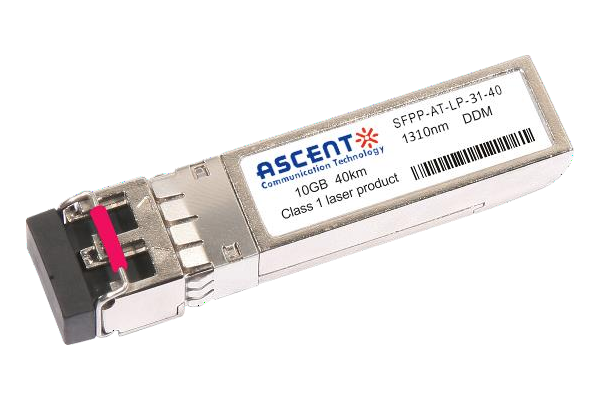
10G SFP+ LR 1310 nm 40 km

10G SFP+ LR 1310 nm 20 km
10G SFP+ LR 1310 nm 10 km

10G SFP+ LRM 1310 nm 2 km
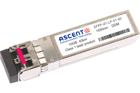
10G SFP+ ER 1550 nm 40 km
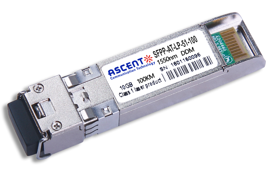
10G SFP+ CDR 1550 nm 100 km
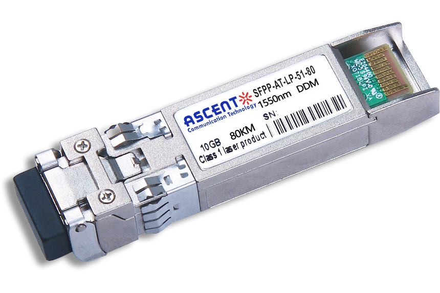
10G SFP+ ZR 1550 nm 80 km
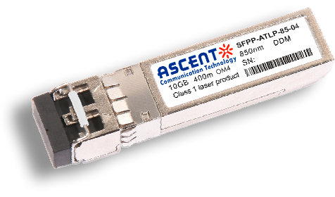
10G SFP+ 850 nm 400 m
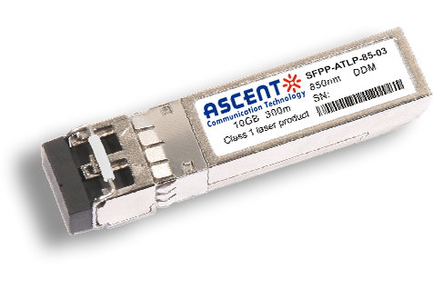
10G SFP+ 850 nm 300 m
10G SFP+ Tunable DWDM 80 km
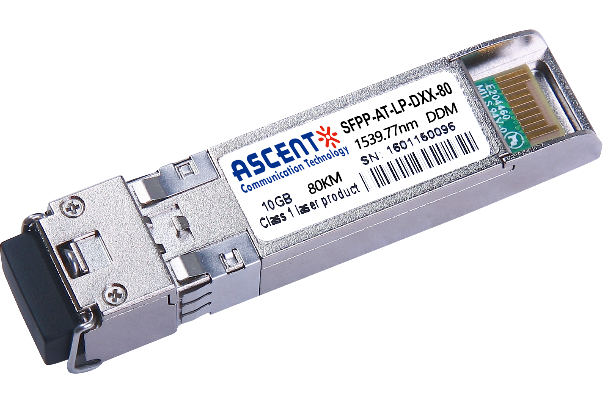
10G SFP+ DWDM 80 km
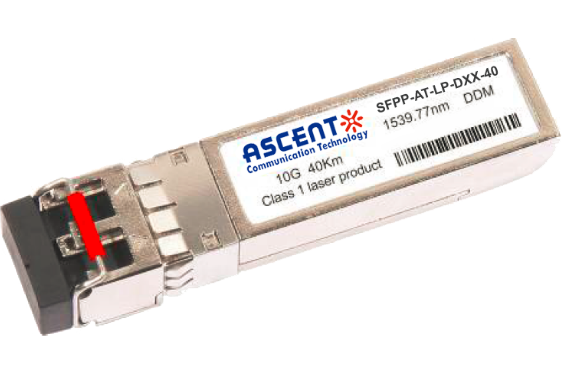
10G SFP+ DWDM 40 km
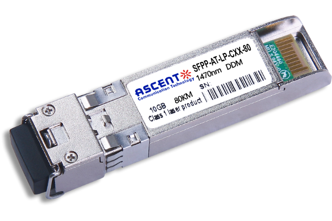
10G SFP+ CWDM 80 km
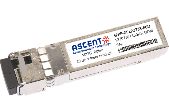
10G SFP+ CWDM 2733 60 km
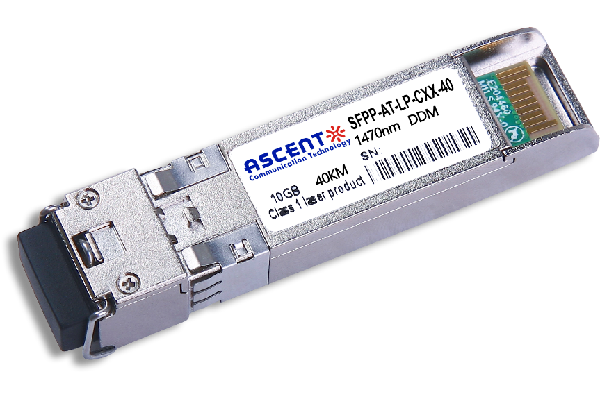
10G SFP+ CWDM 40 km
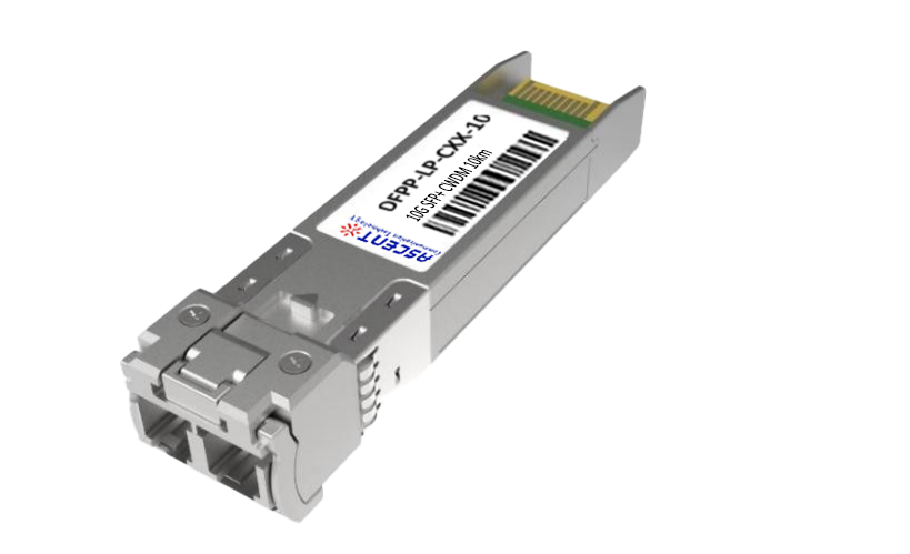
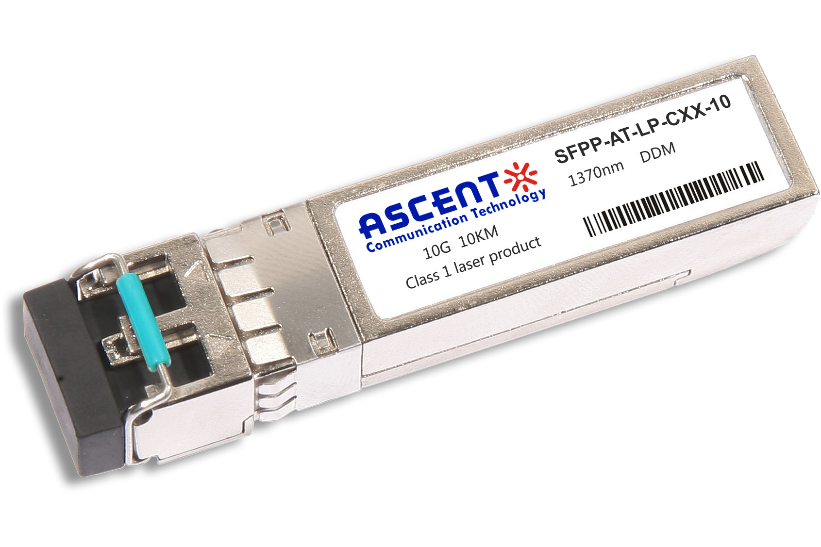
10G SFP+ CWDM 10 km
10G SFP+ Single mode CWDM 10 km
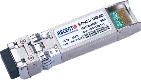
10G SFP+ CWDM 4955 80 km
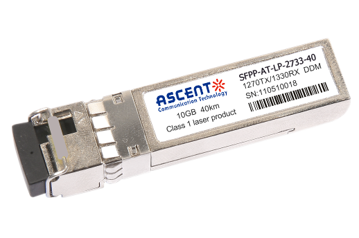
10G SFP+ CWDM 2733 40 km
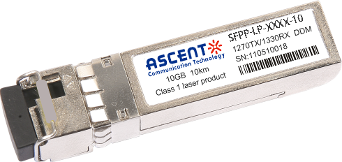
10G SFP+ CWDM 2733 10 km

10G XFP BIDI 80KM

10G XFP BIDI 40KM

10G XFP BIDI 20KM

10G XFP BIDI 10KM

10G XFP LR 1310 nm 20 km

10G XFP LR 1310 nm 10 km
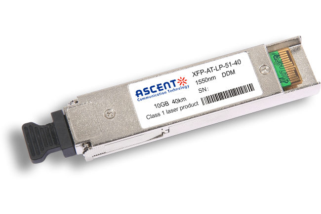
10G XFP ER 1550 nm 40 km

10G XFP ZR 1550 nm 80 km
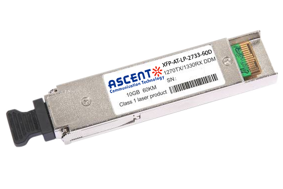
10G XFP CWDM 2633 60 km
10G SFP+ CWDM 1610 80 km
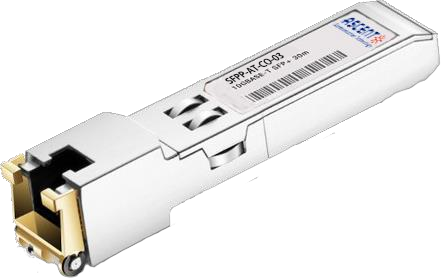
10G SFP+ Copper RJ45 30 m

10G X2 850nm 300m
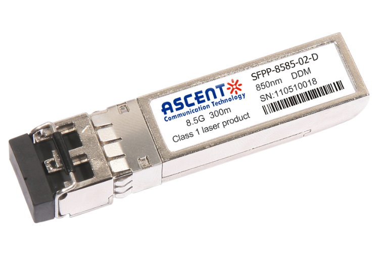
8.5G SFP+ SR 850 nm 150 m
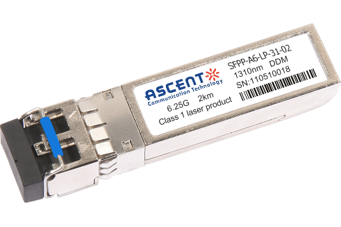
6.25G SFP+ LRM 1330 nm 2 km
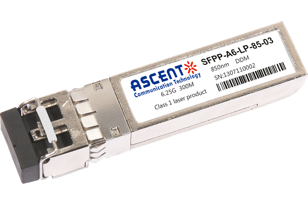
6.25G SFP+ SR 850 nm 300 m
