
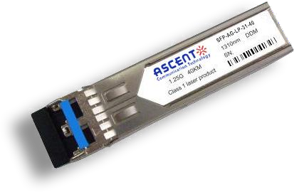
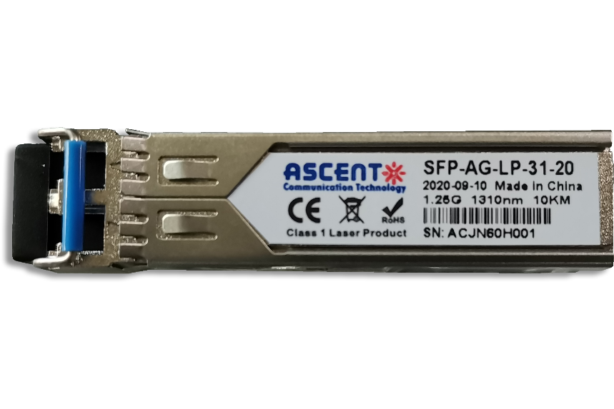
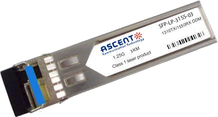
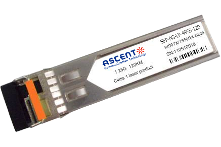
The SFP 2.5Gb/s 1310nm LX transceiver is a compact, high-performance optical module designed for up to 20 km transmission over single-mode fiber (SMF). Supporting data rates up to 2.5 Gb/s, it is ideal for telecom and enterprise applications such as SDH/STM-16, SONET OC-48, and Fiber Channel links. The hot-pluggable SFP form factor ensures easy deployment and flexibility across a wide range of networking platforms. The module utilizes a reliable 1310 nm DFB laser transmitter and a high-sensitivity receiver, providing stable optical performance for medium-reach applications. The optical interface features a duplex LC connector, while the module operates on a standard +3.3V power supply. With low power consumption typically below 1.5W, it offers an efficient and cost-effective solution for 2.5G optical communication. Fully compliant with SFF-8472 digital diagnostic monitoring (DDM), the transceiver enables real-time monitoring of key operating parameters including temperature, voltage, and optical power. Designed for robust operation, it supports both commercial (0°C to 70°C) and industrial (-40°C to 85°C) temperature ranges, and is RoHS compliant and lead-free, making it suitable for carrier-grade and industrial networking environments.
· Up to 2.5Gb/s Data Links
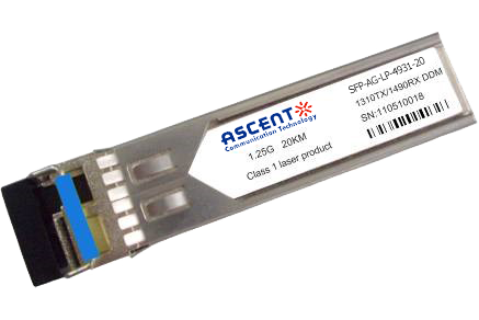
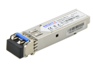
· Hot-Pluggable
· 1310nm DFB laser transmitter
· Duplex LC connector
· Up to 20 km on 9/125pm SMF
· Single +3.3V Power Supply
· Monitoring Interface Compliant with SFF-8472
· Low power consumption<1.5W typically
· Operating temperature range:
Commercial: 0°C to 70°C
Industrial: -40°C to 85°C
· RoHS compliant and Lead Free
Absolute Maximum Ratings
Parameter | Symbol | Min. | Max. | Unit |
Storage Temperature | Ts | -40 | +85 | °C |
Maximum Supply Voltage | Vcc | -0.5 | 4.0 | V |
Operating Relative Humidity | RH | 0 | 85 | % |
Recommended Operating Conditions
Parameter Operating Case Temperature | Symbol Tc | Min. 0 | Typ.
| Max. +70 | Unit °C | Note SFP-2G-LP-31-20 |
-40 | +85 | °C | SFP-2G-LP-31-20A |
Optical Characteristics
Parameter | Symbol | Min. | Typ. | Max. | Unit | Note |
Transmitter | ||||||
Center Wavelength | λc | 1290 | 1310 | 1330 | nm | 1 |
Spectral Width(-20dB) | σ | 1 | nm | |||
Side Mode Suppression Ratio | SMSR | 30 | dB | |||
Optical Output Power | Pout | -9 | -3 | dBm | 2 | |
Optical Rise/Fall Time | tr / tf | 260 | ps | 3 | ||
Extinction Ratio | ER | 8.2 | dB | |||
Total Generated Transmitter Jitter (Peak to Peak) | JTXp-p | 0.07 | UI | 4 | ||
Total Generated Transmitter Jitter (rms) | JTXrms | 0.007 | UI | 4 | ||
Eye Mask for Optical Output | Compliant with IEEE802.3 (class 1 laser safety) | |||||
Receiver | ||||||
Optical Input Wavelength | λc | 1100 | 1600 | nm | ||
Optical Input Power | Pin | -24 | -1 | dBm | 5,6 | |
Receiver Overload | Pol | -3 | dBm | 5,6 | ||
RX Sensitivity | Sen | -24 | dBm | 5,6 | ||
Receiver Reflectance | 12 | dB | ||||
RX_LOS Assert | LOSA | -40 | dBm | |||
RX_LOS Deassert | LOSD | -25 | dBm | |||
RX_LOS Hysteresis | LOSH | 0.5 | 2 | 6 | dB | |
General Characteristics | ||||||
Data Rate | BR | 2500 | 2700 | Mb/s | ||
Bit Error Rate | BER | 10-12 | ||||
Max. Supported Link Length on 9/125μm SMF@2.5G | LMAX | 20 | km | 7,8 | ||
Total System Budget | LB | 16 | dB | 7,8 | ||
Note:
1. Also specified to meet curves in FC-PI 13.0 Figures 18 and 19, which allow trade-off between wavelength spectral widths.
2. Class 1 Laser Safety per FDA/CDRH and EN (IEC) 60825 regulations.
3. Unfiltered 20-80%. Complies with IEEE 802.3 (Gig. E), FC 1x and 2x eye masks when filtered.
4. Measured with DJ-free data input signal. In actual application, output DJ will bethe sum of input DJ and .DJ.
5. Measured with conformance signals defined in FC-PI 13.0 specifications.
6. Measured with PRBS 223-1 at 10-12 BER.
7. Dispersion limited per FC-PI Rev.13.
8. Attenuation of 0.25dB/km is used for the link length calculations. Distances are indicative only. Please refer to the Optical Specifications in Table IV to calculate a more accurate link budget based on specific
conditions in your application.
Electrical Characteristics (Top = Tc, Vcc = 3.135 to 3.465 Volts)
Parameter | Symbol | Min. | Typ. | Max. | Unit | Note |
Supply Voltage | Vcc | 3.14 | 3.30 | 3.47 | V | |
Supply Current | Icc | 300 | mA | |||
Inrush Current | Isurge | Icc+30 | mA | |||
Maximum Power | Pmax | 1.0 | W | |||
Transmitter | ||||||
Input Differential Impedance | Rin | 90 | 100 | 110 | ||
Single Ended Data Input Swing | Vin PP | 200 | 1200 | mVp-p | ||
Transmit Disable Voltage | VD | Vcc-1.3 | Vcc | V | 1 | |
Transmit Enable Voltage | VEN | Vee | Vee+0.8 | V | ||
Transmit Disable Assert Time | Tdessert | 10 | us | |||
Receiver | ||||||
Single Ended Data Output Swing | Vout,pp | 300 | 1000 | mv | 2 | |
Data Output Rise Time | tr | 260 | ps | |||
Data Output Fall Time | tf | 260 | ps | |||
LOS Fault | Vlosfault | Vcc-0.5 | VCC_host | V | 3 | |
LOS Normal | Vlos norm | Vee | Vee+0.5 | V | 3 | |
Power Supply Rejection | PSR | 100 | mVpp | |||
Total Generated Transmitter Jitter(Peak to Peak) Contribution | JRXp-p | 0.07 | UI | |||
Total Generated Transmitter Jitter(Rms) | JRXrms | 0.007 | UI | |||
Note:
1. Or open circuit.
2. Into 100 ohm differential termination.
3. LOS is LVTTL. Logic 0 indicates normal operation; logic 1 indicates no signal detected.


2.5G SFP 1550nm 80km
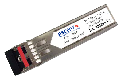
2.5G SFP CWDM 40 km
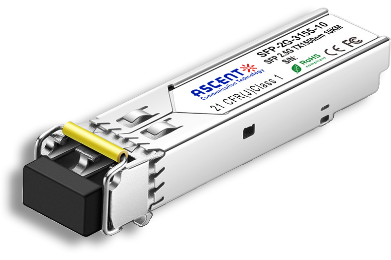
2.5G SFP BiDi 10 km
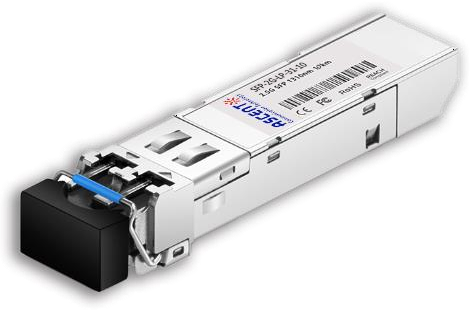
2.5G SFP 1310nm 10km
2.5G SFP 1310 nm 2 km
1.25G SFP EZX 1550 nm 120 km
1.25G SFP ZX 1550 nm 80 km
1.25G SFP EX 1550 nm 40 km
1.25G SFP 1550 nm 160 km
1.25G SFP EX 1310 nm 40 km
1.25G SFP 1310 nm 20 km

1.25G SFP 1310 nm 10 km

1.25G SFP SR 850 nm 550 m

1.25G SFP BX 3155 20 km
1.25G SFP BX 3155 3 km
1.25G SFP BX 4950 120 km

1.25G SFP BX 4950 80 km

1.25G SFP BX 3150 40 km
1.25G SFP BX 3149 20 km
1.25G SFP CWDM 4931 20 km

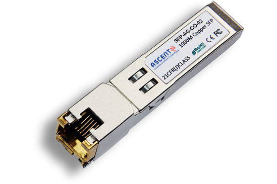
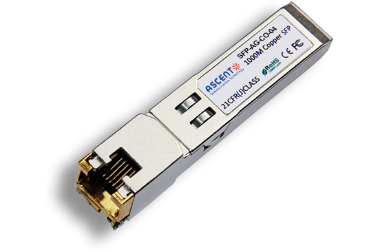
1000M Copper SFP
10/100/1000M Copper SFP

1000M Copper SFP w/ Auto-Negotiation
10/100/1000M Copper SFP w/ Link Indicator
155M SFP 1550 nm 80 km

155M SFP OC3 1310nm 15 km
