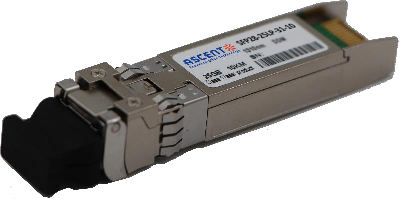
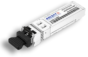
Ascent’s SFP28 transceivers are designed for use in 25G Gigabit Ethernet links with distances up to 10 km over single-mode fiber. These transceivers include a PIN photo detector diode and FP transmitter. Digital diagnostic functions are available via a 2-wire interface.
• Up to 10 km transmission distance
• FP transmitter and PIN photo-detector
• Duplex LC connector
• Metal enclosure, for lower EMI
• Electrical interface compliant to SFF-8431 specifications
• 2-wire interface for management specifications compliant with SFF-8472
• Compliant with SFP+ MSA
• Single 3.3V power supply
• Power dissipation < 1.2W
• Case operating temperature range: Commercial: 0 °C to +70 °C
• Industrial: -40 °C to +85 °C
Parameter | Symbol | Min. | Typ. | Max. | Unit | Note |
Storage Temperature | Ts | ‑40 | ‑ | 85 | °C | |
Relative Humidity | RH | 5 | ‑ | 95 | % | |
Power Supply Voltage | VCC | ‑0.3 | ‑ | 4 | V |
Recommended Operating Conditions
Parameter | Symbol | Min. | Typ. | Max. | Unit | Note |
Case Operating Temperature | Tcase | 0 | ‑ | 70 | °C | Commercial |
‑40 | ‑ | 85 | °C | Industrial | ||
Power Supply Voltage | VCC | 3.14 | 3.3 | 3.47 | V | |
Power Supply Current | ICC | ‑ | ‑ | 300 | mA | Commercial |
‑ | ‑ | 360 | mA | Industrial | ||
Data Rate | BR | 24.3 | 25.78 | 26.5 | Gbps | |
Transmission Distance | TD | ‑ | ‑ | 10 | km | |
Coupled Fiber | Single‑mode fiber | 9/125 µm SMF | ||||
Electrical Characteristics
Parameter | Symbol | Min. | Typ. | Max. | Unit | Note |
Supply Voltage | Vcc | 3.14 | 3.3 | 3.46 | V | |
Supply Current | Icc | 300 | mA | Commercial | ||
360 | mA | Industrial | ||||
Transmitter | ||||||
Input Differential Impedance | Rin | 100 | Ω | 1 | ||
Differential Data Input Swing | Vin,pp | 180 | 800 | mV | ||
Transmit Disable Voltage | VDIS | Vcc‑1.3 | Vcc | V | ||
Transmit Enable Voltage | VEN | Vee | Vee+ 0.8 | V | 2 | |
Receiver | ||||||
Differential Data Output Swing | Vout,pp | 300 | 850 | mV | 3 | |
LOS Fault | VLOS fault | Vcc‑1.3 | VCCHOST | V | 4 | |
LOS Normal | VLOS norm | Vee | Vee+0.8 | V | 4 |
Notes:
1. Connected directly to TX data input pins. AC coupled thereafter.
2. Or open circuit.
3. Into 100 Ω differential termination.
4. Loss Of Signal is LVTTL. Logic 0 indicates normal operation; logic 1 indicates no signal detected.
Optical Characteristics
Parameter | Symbol | Min. | Typ. | Max. | Unit | Note |
Transmitter | ||||||
Average Output Power | POUT | ‑5 | 2 | dBm | 1 | |
Optical Wavelength | λ | 1295 | 1325 | nm | ||
Spectral Width (RMS) | σ | 1 | nm | |||
Optical Extinction Ratio | ER | 3.5 | dB | |||
Receiver | ||||||
Rx Sensitivity | RSEN | ‑13.3 | dBm | 2 | ||
Input Saturation Power (Overload) | PSAT | 0.5 | dBm | |||
Input Optical Wavelength | λC | 1295 | 1325 | nm | ||
LOS De ‑Assert | LOSD | ‑14 | dBm | |||
LOS Assert | LOSA | ‑30 | dBm | |||
LOS Hysteresis | 0.5 | dB |
Notes:
1. Class 1 Laser Safety per FDA/CDRH and IEC‑825‑1 regulations.
2. Measured with a PRBS 231‑1 test pattern @ 25.78 Gb/s, BER @ 5*10‑5.


64G SFP56 850nm 100m
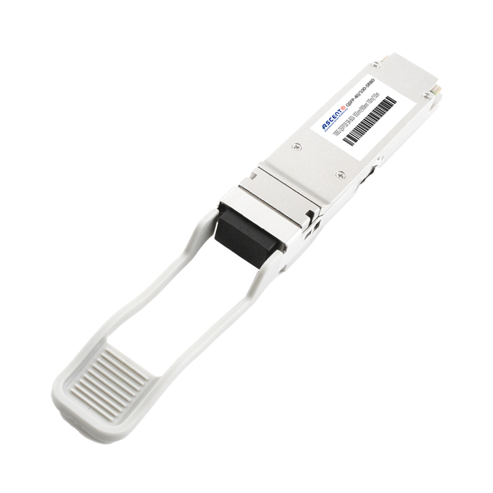
40/100G SFP28 SWDM4 100m

40G QSFP+ ER4 Industrial 40 km

40G QSFP+ ER4 40 km

40G QSFP+ LR4 Industrial 10 km

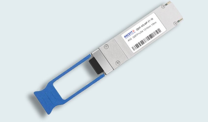
40G QSFP+ LR4 10 km

40G QSFP+ PSM4 2 km
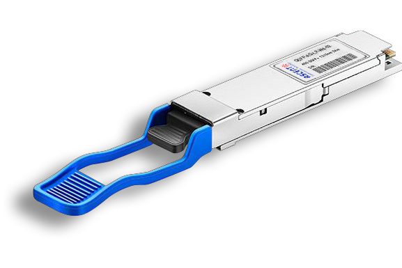
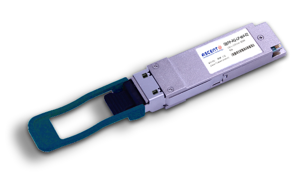
40G QSFP+ PLR4 1310 nm 10 km

40G QSFP+ CSR4 300m
40GBASE-UNIV QSFP+ MMF and SMF
40G QSFP+ CWDM 2 km
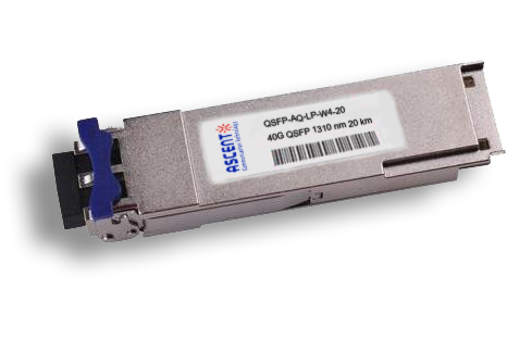
40G QSFP CWDM 20 km
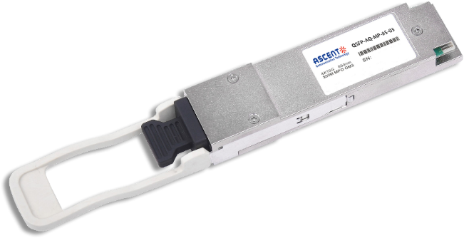
40G QSFP+ SR4 300 m
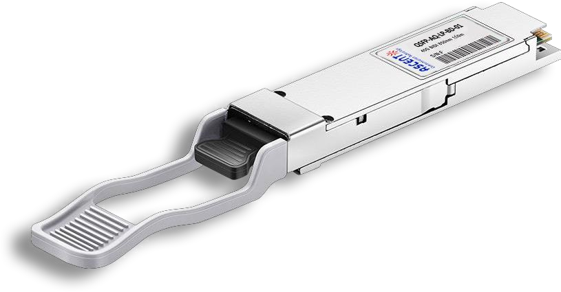
40G QSFP+ BIDI 150m
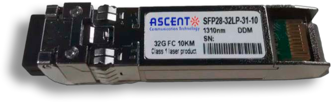
32G SFP28 1310 nm 10 km

32G SFP28 SR 850 nm 100 m
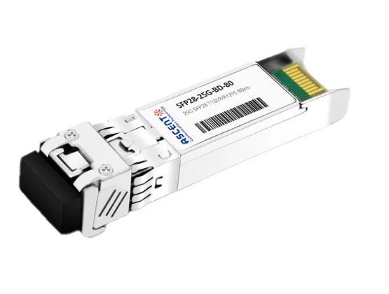
25G SFP28 BIDI 80 km
.png)
25G SFP28 CWDM 10 km(E)
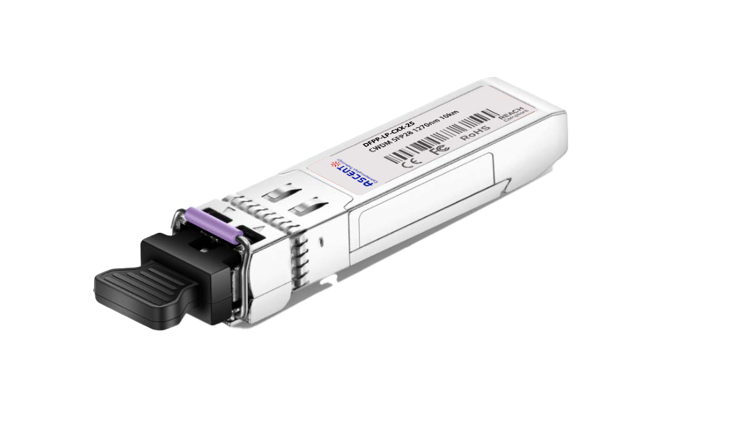
25G SFP28 CWDM 10 km(D)
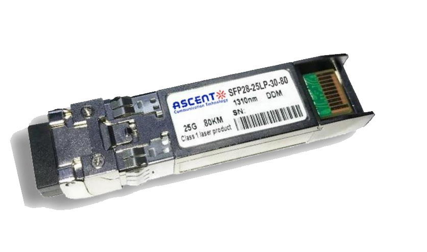
25G SFP28 ZR 1310nm 80km
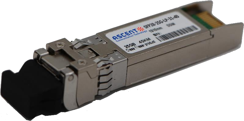
25G SFP28 1310 nm 40km
25G SFP28 850 nm 300m

10/25G SFP28 1310nm 40km
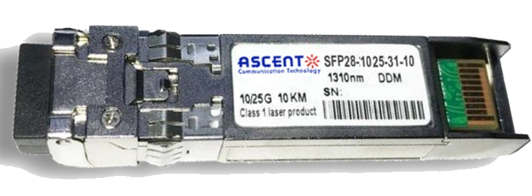
10/25G SFP28 1310nm 10km

10/25G SFP28 850 nm 300m

10/25G SFP28 850 nm 100m
