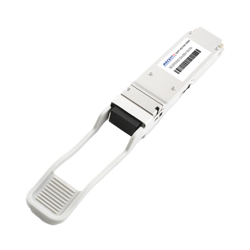
The QSFP28 Bi-Directional transceiver is a high-performance optical module designed for 40G and 100G Ethernet applications over multimode fiber. Supporting transmission distances of up to 70 m on OM3 and 100 m on OM4, the module enables cost-effective high-speed connectivity while allowing reuse of existing duplex LC fiber infrastructure, making it ideal for data center and enterprise network deployments. The module utilizes dual-wavelength VCSEL technology (850 nm / 910 nm) with bi-directional transmission over a single LC fiber pair. Internally, it converts multiple electrical lanes into PAM4 2×50 Gb/s or NRZ channels, delivering an aggregate bandwidth of up to 100 Gb/s. The integrated clock and data recovery (CDR) ensures stable signal integrity, while the QSFP28 electrical interface complies with industry standards for seamless system integration. Designed for high-density environments, the transceiver features low power consumption, hot-pluggable QSFP28 form factor, and digital diagnostic monitoring (DDM) for real-time performance visibility. With its compact design, reliable operation, and compatibility with existing cabling systems, the module provides an efficient solution for switch-to-switch interconnects, data aggregation, and high-speed optical links in modern data center and telecom networks.
· Compliant to the 40/100GbE XLPPI electrical specification per IEEE 802.3bm
· Compliant to QSFP28 SFF-8636 Specification and QSFP28 MSA
· Aggregate bandwidth of > 100Gbps
· Dual wavelength VCSEL bi-directional optical interface, PAM4 2 × 50-Gb/s or NRZ 2x20G 850nm/910 nm
· Capable of over 70m transmission on OM3 Multimode Fiber (MMF) and 100m on OM4 MMF
· Single +3.3V power supply operating
· With digital diagnostic functions
· Temperature range 0°C to 70°C
· RoHS Compliant Part
· Utilizes a standard LC duplex fiber cable allowing reuse of existing cable infrastructure
Parameter | Symbol | Min. | Max. | Unit |
Storage Temperature | TS | -40 | +85 | °C |
Supply Voltage | VCCT, R | -0.5 | 4.0 | V |
Relative Humidity | RH | 0 | 85 | % |
Parameter | Symbol | Min. | Typ. | Max. | Unit |
Operating Case Temperature | TC | 0 | +70 | °C | |
Power Supply Voltage | VCCT, R | +3.13 | 3.3 | +3.47 | V |
Power Supply Current | ICC | 1000 | mA | ||
Max Power Consumption | PD | 3.5 | W |
Parameter | Symbol | Min. | Typ. | Max. | Unit | Note |
Transmitter | ||||||
Optical Wavelength CH1 | λ | 832 | 850 | 868 | nm | |
Optical Wavelength CH2 | λ | 882 | 910 | 918 | nm | |
RMS Spectral Width | Pm | 0.5 | 0.65 | nm | ||
Average Optical Power per Channel | Pavg | -6 | -1 | +4.0 | dBm | |
Laser Off Power Per Channel | Poff | -30 | dBm | |||
Optical Extinction Ratio | ER | 3.0 | dB | |||
Relative Intensity Noise | Rin | -128 | dB/HZ | 1 | ||
Optical Return Loss Tolerance | 12 | dB | ||||
Receiver | ||||||
Optical Center Wavelength CH1 | λ | 882 | 910 | 918 | nm | |
Optical Center Wavelength CH2 | λ | 832 | 850 | 868 | nm | |
Receiver Sensitivity per Channel | R | -8 | dBm | |||
Maximum Input Power | PMAX | +0.5 | dBm | |||
Receiver Reflectance | Rrx | -15 | dB | |||
LOS De-Assert | LOSD | -10 | dBm | |||
LOS Assert | LOSA | -30 | dBm | |||
LOS Hysteresis | LOSH | 0.5 | dB |
Parameter | Symbol | Min. | Typ. | Max. | Unit | Note |
Data Rate per Channel | 25.78125/ 10.3125 | Gbps | ||||
Power Consumption | - | 2.5 | 3.5 | W | ||
Supply Current | Icc | 0.75 | 1.0 | A | ||
Control I/O Voltage-High | VIH | 2.0 | Vcc | V | ||
Control I/O Voltage-Low | VIL | 0 | 0.7 | V | ||
Inter-Channel Skew | TSK | 150 | Ps | |||
RESETL Duration | 10 | Us | ||||
RESETL De-assert time | 100 | ms | ||||
Power On Time | 100 | ms | ||||
Transmitter | ||||||
Single Ended Output Voltage Tolerance | 0.3 | 4 | V | 1 | ||
Common mode Voltage Tolerance | 15 | mV | ||||
Transmit Input Diff Voltage | VI | 120 | 1200 | mV | ||
Transmit Input Diff Impedance | ZIN | 80 | 100 | 120 | ||
Data Dependent Input Jitter | DDJ | 0.1 | UI | |||
Data Input Total Jitter | TJ | 0.28 | UI | |||
Receiver | ||||||
Single Ended Output Voltage Tolerance | 0.3 | 4 | V | |||
Rx Output Diff Voltage | Vo | 600 | 800 | mV | ||
Rx Output Rise and Fall Voltage | Tr/Tf | 12 | ps | 1 | ||
Total Jitter | TJ | 0.7 | UI | |||
Deterministic Jitter | DJ | 0.42 | UI | |||
Note1: 20~80%.


64G SFP56 850nm 100m

40G QSFP+ ER4 Industrial 40 km

40G QSFP+ ER4 40 km

40G QSFP+ LR4 Industrial 10 km

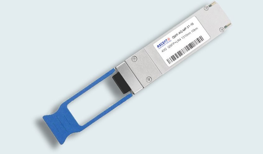
40G QSFP+ LR4 10 km

40G QSFP+ PSM4 2 km
40G QSFP+ PLR4 1310 nm 10 km

40G QSFP+ CSR4 300m
40GBASE-UNIV QSFP+ MMF and SMF
40G QSFP+ CWDM 2 km
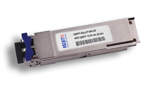
40G QSFP CWDM 20 km
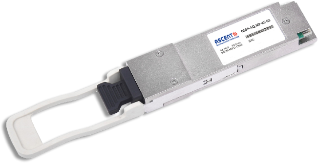
40G QSFP+ SR4 300 m
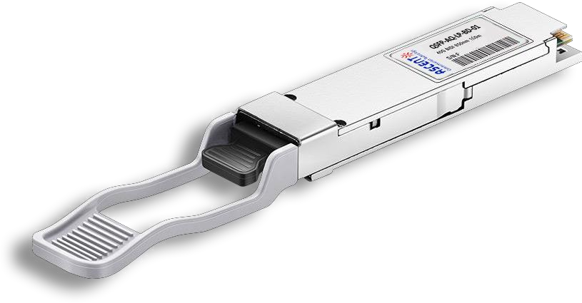
40G QSFP+ BIDI 150m
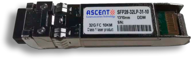
32G SFP28 1310 nm 10 km

32G SFP28 SR 850 nm 100 m
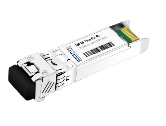
25G SFP28 BIDI 80 km
.png)
25G SFP28 CWDM 10 km(E)
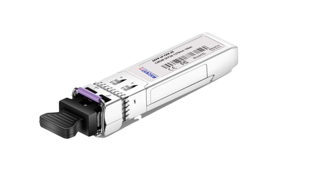
25G SFP28 CWDM 10 km(D)
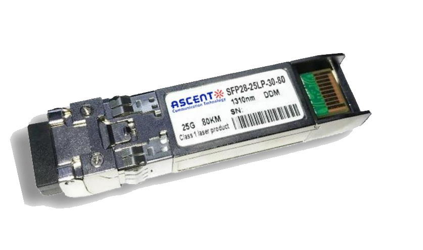
25G SFP28 ZR 1310nm 80km
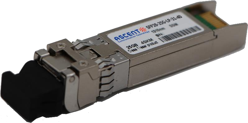
25G SFP28 1310 nm 40km
25G SFP28 1310 nm 10 km
25G SFP28 850 nm 300m

10/25G SFP28 1310nm 40km
10/25G SFP28 1310nm 10km

10/25G SFP28 850 nm 300m

10/25G SFP28 850 nm 100m
